What is Error Detection Correction, LDPC, BCH, Reed-Solomon Algorithm?

Error Detection and Correction in NAND Flash Memory
The current age of information underscores the need, not only of speed but also of accuracy, whether one is storing, retrieving, transmitting or analyzing data. Considering the amount of critical information being generated by the minute, even the slightest of errors can spell disaster. As flash memory moves to smaller geometries, error bits also increase, requiring more powerful error correction algorithms to ensure the reliability of the flash storage device.
Bad Blocks
Bad blocks are blocks that have one or more invalid bits. They may be unusable or weak and prone to errors. They may be present even in new devices and may develop during the lifetime of the device.
There are two types of bad blocks in a NAND flash storage device:
Initial bad blocks. NAND flash devices may ship out with a number of bad blocks. Before the device is shipped, the location of bad blocks is mapped, and a bad block management algorithm is usually implemented, where a bad block table is created by reading all the spare areas in the flash storage device. Invalid blocks are identified during testing and validation in the factory. The bad block table is saved in a good block, so it can be loaded by the device on reboot (Micron).
Accumulated or Later Bad Blocks. As the device goes through the rigors of its use, data in the good blocks may be lost or corrupted due to wear out during its lifetime, leading to read/write disturb errors, retention errors, and other issues. Consequently, damaged blocks cause stored data to be inaccessible and applications or operating systems may fail to open. As bad blocks increase, drive capacity decreases and performance is compromised, eventually resulting in device failure.
NAND Flash Degradation and Bit Errors
Error correction codes are employed to detect and correct bit errors. In the early days of flash, single-digit error codes were used, but as scaling became prevalent, cell size decreased and bits per cell increased. The following factors impact flash degradation and the rise of bit errors.
Program/Erase (P/E) Cycles. The constant cycles of programming (writing) and erasing require the application of high voltage to the NAND cell, causing stress on and weakening the Tunnel Oxide.
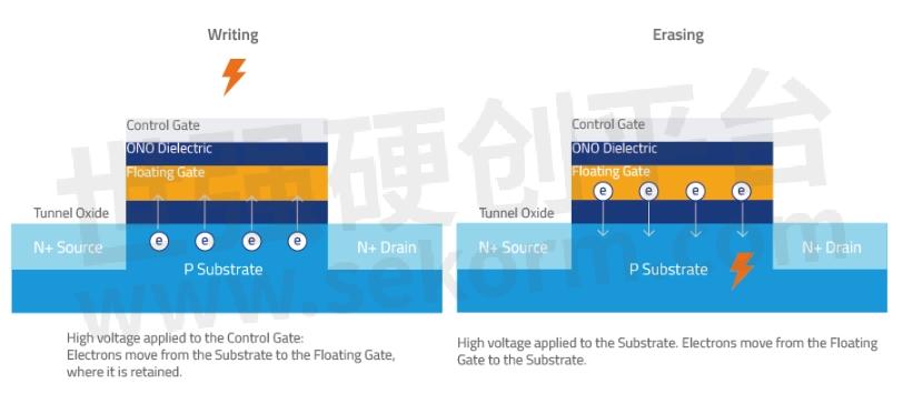
Figure 1. Program (write) and erase operations on the NAND flash cell require the application of high voltage, which causes stress on the Tunnel Oxide. As P/E cycles increase, the Tunnel Oxide weakens, causing electrons to leak out from the Floating Gate and the NAND flash cell to degrade.
More bits per cell. In efforts to increase density, new flash technologies have enabled the storing of more bits in a cell, narrowing the gap between voltage threshold (VT) distributions, resulting in voltage shifts and causing bit errors due to cell-to-cell interference.
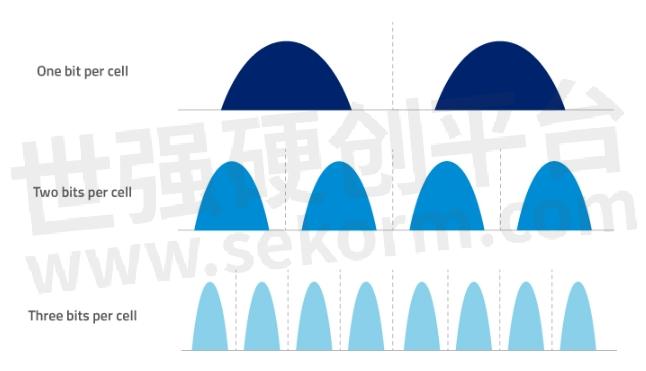
Figure 2. More bits stored per cell deliver increased density/capacity, but also increases cell-to-cell interference, as cells get crammed more closely together. A read or write to one cell may impact other neighboring cells, and cause bit errors.
Error Detection and Correction in ATP NAND Flash Storage Devices
Error correction codes (ECC) are techniques used to correct errors in the NAND flash, allowing recovery of data that may be corrupted due to bit errors. Internal ECC mechanisms can detect/correct up to a certain number of errors.
An example of ECC employed by other flash storage products is the Hamming Code. Invented in 1950 and named after its inventor, Richard Hamming, this algorithm can detect and correct 1-bit errors but can only detect and not correct 2-bit errors. It is easy to implement due to its limited error correcting abilities and is widely used in single-level cell (SLC) flash, which is simpler in architecture and only requires single-bit ECC. A popular Hamming code is 7, 4 where, in a 7-bit block, only 4 bits are made up of data and the other 3 bits are error correction codes.
Below is a sample implementation of the Hamming Code on a 2 KB page with 2048 bytes of user data. (In flash storage devices where page size is over 512 bytes, the data is divided into sections of 512 bytes with a Hamming code used for each 512-byte section.
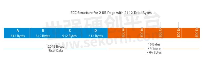
Figure 3. Sample Hamming Code implementation for a 2 KB page. The Hamming Code for each 512 KB section is stored in the Spare area.
While some products available in the market use only simple Hamming codes, ATP products employ
advanced ECC that can correct multiple bit errors.
The following section introduces the error detection and correction mechanisms applied in ATP's flash storage devices:
Reed-Solomon Algorithm
Invented in 1960 by engineers Irving Reed and Gustave Solomon, both engineers at MIT's Lincoln Labs, the Reed-Solomon algorithm involves the addition of extra/redundant data to a block of digital data. It is commonly used in hard disk drives and compact discs, as well as NAND flash storage where it is often used to handle NAND flash bit-flipping. A bit flip occurs when an operation on one cell causes disturbances on another cell due to the proximity of memory cells built too close to each other. When a bit flip happens, the floating gate of a cell may gain (get programmed) or lose (get erased) electrons due to the disturbance in another cell.
Reed-Solomon codes correct symbols and is thus considered excellent for applications where errors tend to be clustered together. The Reed-Solomon algorithm is widely used to correct multiple-bit errors in a single page but may perform poorly with large message blocks, greatly amplifying the time to encode or decode the data when the block size is doubled.
A popular Reed-Solomon code is RS (255, 247) with 8-bit symbols. Each code word contains 255 code word bytes, of which 247 bytes are data and 8 bytes are parity. The decoder can correct any 4 symbol errors in the code word.
Currently, some ATP flash products implement Reed-Solomon encoding using a 4-byte-on-512-byte encoding. This means the ECC mechanism on these products can correct at least 4 bits error for every 512B. However, in a best-case scenario, it can correct up to 32 bits error per 512B, as long as these 32 bits error are located within same 4 symbols.
BCH (Bose, Chaudhuri, Hocquenghem) Algorithm
BCH codes were invented in 1959 by Alexis Hocquenghem, and independently in 1960 by Raj Bose and D.K. Ray-Chaudhuri. BCH codes can correct multiple-bit errors and can handle both random and burst errors. The main advantage of BCH codes is that they can be easily decoded using a method called "syndrome decoding." BCH codes require a low amount of redundancy and are widely used in satellite communications, compact disc drives and bar codes.
In contrast to the Reed-Solomon algorithm, which provides more robust error correction ability but requires a large amount of system resources to implement, the BCH algorithm is becoming popular because of its improved efficiency, being able to detect both highly concentrated and widely scattered errors. Another advantage is that the encoding and decoding techniques are relatively simple and BCH codes require a low amount of redundancy.
LDPC (Low Density Parity Check)
LDPC codes, also known as Gallagher codes in honor of its developer Robert G. Gallagher, are powerful error correcting algorithms first proposed in the 1962 PhD thesis at MIT but have been gaining wide implementation only about 10 years ago. They are increasingly being used in the enterprise world for their ability to decode both soft-bit data and hard-bit data. In Gallagher's thesis, low density parity code is defined as "a linear binary block for which the parity check matrix of interest has a low density of ones," meaning there are fewer 1s compared to the 0s).
Advantages of LDPC over other algorithms:
Low decoding complexity
Uses both hard-bit and soft-bit information from the NAND flash during decoding
Demonstrates good performance with short blocks
Delivers "near-capacity" performance with long blocks. (Near capacity refers to the Shannon limit, which is the maximum rate at which data can be sent over a channel with close to or approaching zero error.)
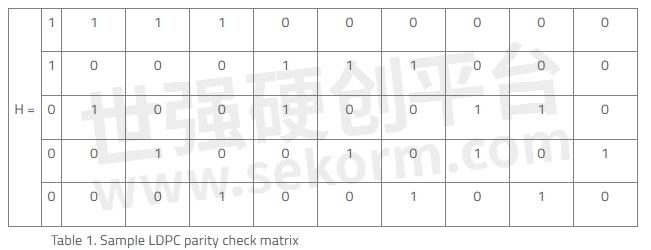
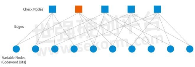
Figure 4. A Tanner graph shows a graphical representation of the LDPC code for the given parity check matrix in Table 1 and helps describe the decoding algorithm. "Check Nodes" represent the number of parity bits, and "Variable Nodes" represent the number of bits in a codeword. An edge connects a bit node to a check node only if the bit is included in the parity check.
Summary
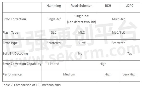
The following table provides a comparison of the ECC algorithms discussed in this article.
(Source: Error Correction Codes in NAND Flash Memory)
As NAND flash lithography scales down, cell geometries shrink and cells store more bits per cell, densities increase but so do error bits. To ensure the reliability of its industrial flash storage products, ATP employs advanced error detection and correction technologies.
- +1 Like
- Add to Favorites
Recommend
- ATP Offers Typical SSD Form Factors, NAND Flash Technologies and Interfaces
- News | NAND Flash Storage Solutions for the Data-Driven 5G Era | ATP
- SMART‘s DuraFlash RU350 Enterprise USBs are Offered with Triple-Level Cell (TLC) 3D NAND Flash
- Ensuring NAND Flash and Data Integrity of Dashcam Memory Cards (Part 2)
- FORESEE Debuts 512Mb SPI NAND Flash in Chinese Mainland,Which Has a 8mm×6mm SPI NAND Flash Packaging and a Smaller Packaging—6mm×5mm
- Alliance Memory Introduces New Line of 1.8V and 3.3V SLC Parallel NAND Flash Memory Solutions, Compliant With the ONFI 1.0 Specification
- The 1.8V and 3V SPI NAND Flash Memory: Alliance Memory AS5F Series with Densities from 1G to 8G
- ATP Offers 3D NAND Flash in Various Form Factors With Capacities Ranging From 128 Gb to 1 Tb, Better Than Planar Nand Solutions
This document is provided by Sekorm Platform for VIP exclusive service. The copyright is owned by Sekorm. Without authorization, any medias, websites or individual are not allowed to reprint. When authorizing the reprint, the link of www.sekorm.com must be indicated.
Integrated Circuits


Discrete Components


Connectors & Structural Components


Assembly UnitModules & Accessories


Power Supplies & Power Modules


Electronic Materials


Instrumentation & Test Kit


Electrical Tools & Materials


Mechatronics


Processing & Customization


