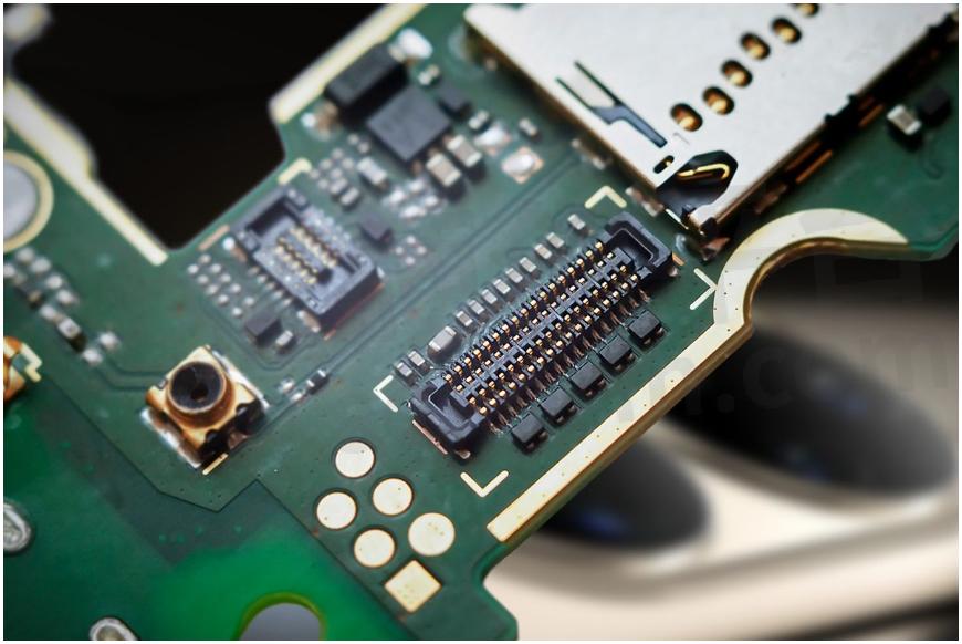
Testing and Common Troubleshooting of Board-to-Board PCB Connectors

Board-to-board PCB Connector Testing and Inspection
Observe that the voltage applied to the connector does not exceed 50% of its rated voltage. For the installation size of the connector, for the insertion header, the length of the soldering feet on the soldered PCB must be exposed to the part of the PCB plate larger than 0.5mm. For more precise connectors, if possible, choose models with slightly positioned pins in PCB space for ease of manual soldering. Check if there is any polarity design. Check whether lead is present in the materials used for the board-to-board PCB connector. For small-volume connectors with low-contact pressure, used in low-current and voltage situations, it is recommended to use gold or silver-plated connectors to prevent film layer resistance from affecting the signal. Pay attention to the height of the board-to-board PCB connector after assembly, and whether it meets the soldering height of the elements around the PCB. The mating height must be greater than the soldering height of the elements around the PCB, and ensure that there is a certain margin to ensure that no interference occurs, especially when considering the possibility of height error of the elements after PCB soldering.
Board-to-board connection problems and common fault handling, and properly connecting board-to-board PCB connector products can improve the life of the product and ensure the good operation of mechanical equipment. If the board-to-board product fails and is not handled in a timely manner, it will bring immeasurable economic losses. Below is a brief introduction to the connecting and fault-handling methods of board-to-board connector circuits.
About the Connection of Board-to-Board PCB Connectors
The board-to-board plug socket is used to electrically connect two separated circuit boards, which includes the first connector connected to the circuit board and the adapter connector used to connect the first connector in series. The first connector has a first terminal connected to the circuit board and a body for holding the first terminal. The adapter connector has a second terminal and a body for holding the second terminal. The two extended ends of the second terminal can be inserted to cooperate with the first terminal on the two connectors located on the two circuit boards to achieve electrical conduction. One end of the first terminal and the second terminal have a reverse-bent elastic part, and the body and the second terminal can select a suitable extension length according to the standard distance setting of the circuit board.
About the Troubleshooting of Board-to-board PCB Connectors
When a product fails, the cause can be identified as wire breakage, product loosening, and other issues. Wire breakage in the middle is not very common; most often, it occurs at the connector. Therefore, the focus of inspection should be on the wires at the sensor and connector sequence to check for looseness, poor contact, and other issues. Generally, open circuit faults caused by poor contact are mostly due to rust on the product’s end, and dirt entering the terminal or connector socket, which in turn leads to a decrease in contact pressure. To address this issue, the connector needs to be removed and then reinserted to change its connection status, restoring normal contact.

- +1 Like
- Add to Favorites
Recommend
- ept One27® SMT PCB Connectors with a Pitch of 1.27mm is Suitable for Board-to-board Applications ∣ video
- Function and Parameter Selection of Board-to-Board Connectors
- How to Select Board-to-board Connectors?
- Inspection and Connection Troubleshooting of Board-to-Board Connectors
- What Should Be Noted When Testing Board-to-Board Power Connectors?
- Features and Classifications of Board-to-Board Connectors
- Features and Benefits of Automotive Board-to-Board Connectors
- Basic Performance of Board-to-Board Connectors
This document is provided by Sekorm Platform for VIP exclusive service. The copyright is owned by Sekorm. Without authorization, any medias, websites or individual are not allowed to reprint. When authorizing the reprint, the link of www.sekorm.com must be indicated.


