NOVOSENSE Automotive-qualified CAN Interface Chip Boosts Smart Control of Vehicle

Common vehicle bus
As the control of each system in the vehicle is becoming smarter and more automated, the electrical system of the vehicle is getting more and more complex. Data exchange is required between the functional systems of the vehicle, the functional system, and the vehicle display instrument, as well as the functional system and the vehicle fault diagnosis system. Traditional point-to-point data exchange methods may result in complicated wiring systems and a high failure rate. Therefore, vehicle manufacturers have studied and defined various vehicle bus standards to reduce the complexity of the wiring harness network, the failure rate of the electronic system, and the cost of the vehicle. Among them, the CAN bus is the most widely used.
Features of CAN bus
Signal transmission: Differential transmission adopted for strong anti-interference ability and application in strong interference environment in the vehicle
Communication speed: Transmission rate of up to 10kbps~5Mbps to meet the requirements of most applications in the vehicle
Flexible system: Nodes to be added without any software or hardware change
Multi accesses: Multi-host broadcast structure available
Information transmission: Fixed message format with priority automatically arbitrated by multiplex ID node
Error detection: Error detection is provided to resend the error and check and receive the CRC automatically with very low data error
Based on the above characteristics, the CAN bus can be used for real-time and reliable data transmission and normal communication of vehicle network; In addition, the industrial chain of the CAN chip is pretty complete in respect of production, communication standard protocols, software tool support, and application, which plays a very important role in automotive applications.
Application circuit reference of CAN system
Increased electronic components in the vehicle bring high electromagnetic interference for both the vehicle and the systems on it. Different from traditional vehicles, new energy vehicles use electric drive systems for driving. Switching of high-power devices causes large voltage and current mutations when charging and discharging, probably causing serious EMC problems, and bringing high EMC performance requirements for bus interface chips widely used in vehicles. For better EMC performance, the complement and perfection of the peripheral circuit in the system are also very important in addition to chip design. The following is a typical application circuit diagram of the CAN transceiver system:
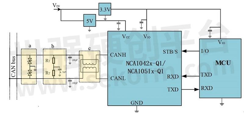
Typical Application Circuit Diagram of the CAN Transceiver System
Due to the common-mode high resistance and differential-mode low resistance characteristics of the common-mode inductor, placing the common-mode inductor near the transceiver bus (frame c, recommended value: 100uH) can effectively filter out the high-frequency noise outside the bus and the common-mode noise generated by the CAN transceiver due to signal asymmetry, without affecting the transmission quality of CAN differential signal. Therefore, it can improve the anti-interference ability of the system and reduce the EMI of the system.
A capacitor to ground (100pF recommended) can be placed for the bus to effectively filter out the transient overshoot of the vehicle CAN bus (such as ESD, ISO7637 pulse, etc.) provided that the system speed and load quantity are not affected.
It is recommended that the 120Ω terminal matching resistors of the bus be composed in series by two 60Ω resistors and grounded by the capacitor (4.7nF recommended) at the middle connection point. This helps to improve signal consistency between CANH and CANL buses, reduce EMI, and direct the common-mode interference here to the ground to reduce the interference to the bus.
Since systems on the vehicle have high ESD requirements, a dedicated ESD protection device (frame a such as PESD2CAN) with a small parasitic capacitor placed near the bus interface can effectively enhance the ESD protection of the chip.
In addition, the errors of bus connection load capacitance and matching resistance should be as small as possible to avoid common mode interference caused by bus signal asymmetry.
Introduction to NOVOSENSE CAN transceiver chip
German C&S Authoritative Recognition
NOVOSENSE has obtained the German C&S conformance report for its automobile-qualified CAN chip (NCA1042x-Q1/NCA1051x-Q1). The German C&S Laboratory is recognized as the authoritative certification body in the industry, which can test whether the onboard chip can achieve connectivity and compatibility in the network. Obtaining the C&S conformance report means that the automobile-qualified CAN chip of NOVOSENSE can realize the upstream and downstream interconnection and free networking with the CAN interface of any other brand that has obtained the certification.
Performance Advantages
High transmission rate and high stability
The NCA1042x-Q1/NCA1051x-Q1 CAN transceiver chip of NOVOSENSE can operate stably in the wide temperature range from -40℃ to +125℃, with a data transmission rate of up to 5Mbps, CAN FD supported in full series, and common package in the industry for excellent EMC performance.
Low power consumption and high reliability
NCA1042x-Q1 provides Standby mode with low current, which can be woken up by the master controller or bus, while NCA1051x-Q1 provides Silent mode with low power consumption, and both are disconnected from the bus after power failure. In addition, both NCA1042x-Q1 and NCA1051x-Q1 enable TXD timeout in normal mode, NCA1042x-Q1 supports bus timeout in standby mode, the bus voltage of both ranges from -58V to +58V, and both support over-temperature and over-current protection.
Wide I/O voltage operating range
The chip logic I/O operating voltage of NCA1042B-Q1 and NCA1051A-Q1 CAN transceiver ranges from 2.8 to 5.5V, supporting MCU I/O levels of 3.3V and 5V.
Functional Diagrams
NCA1042x-Q1/NCA1051x-Q1
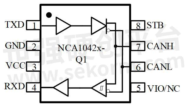
NCA1042x-Q1/NCA105x-Q1 Functional Diagrams
The NCA1042x-Q1/NCA105x-Q1 is a high-speed CAN transceiver that provides an interface between the controller with Local Area Network (CAN) protocol and the physical two-wire CAN bus, supporting at least 110 CAN nodes
Compatible with the CAN physical layer structure defined in ISO 11898-2:2016 and SAE J2284-1 to SAE J2284-5
Support CAN FD, and realize reliable communication in fast phase network, with a data rate of up to 5Mbps
Provide thermal protection and explicit timeout for data transmission
Product parameter comparison
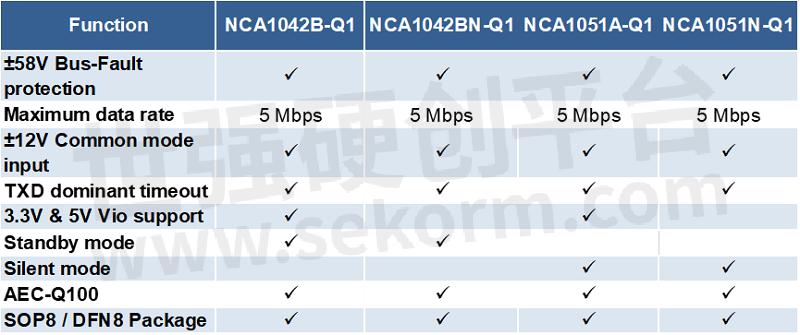
NCA1042x-Q1/NCA105x-Q1 Product Parameter Comparison
P/N information
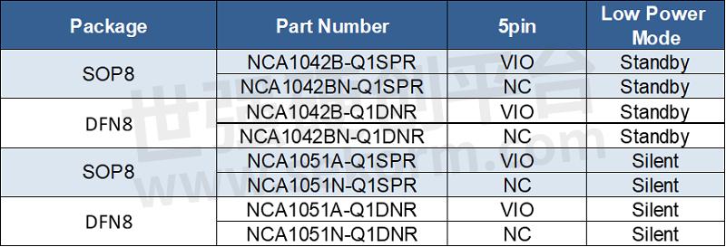
NCA1042x-Q1/NCA105x-Q1P/N Information
NOVOSENSE Automotive-qualified CAN Interface Chip NCA1042x-Q1/NCA1051x-Q1 are both P2P-compatible with mainstream chips in the market. Users can directly replace them without modifying the design, flexibly meeting user's selection requirements, with higher cost performance and a more reliable supply guarantee.
- +1 Like
- Add to Favorites
Recommend
- Integrated Isolated Power 3CH Digital Isolated Solution of NOVOSENSE for Both High Performance and Cost Effectiveness
- NOVOSENSE Boosts Energy and Power Supply Business Through Comprehensive PV Solutions
- NOVOSENSE Has Launched Multiple Automobile-qualified Chips with Breakthrough Innovation Technology In the first half of 2022!
- NOVOSENSE Assists the Formulation of LIN Transceiver Chip Standard, Promoting the High-quality Development of the Automotive Chip Industry
- NOVOSENSE Won VDE Premium Quality Award for High Quality Development
- NOVOSENSE Released a New 1200V Series SiC Diode with Typical Fowrard Voltage of 1.39V, Contributing to the SiC Ecosystem
- NOVOSENSE NST1002 Temperature Sensor Facilitates Accurate CGM Measurement with Glucose Monitoring Black Technology
- NOVOSENSE‘s New Isolation Voltage Sampling Chips NSI1312x Series Support +1.2V Bidirectional Linear Input Voltage
This document is provided by Sekorm Platform for VIP exclusive service. The copyright is owned by Sekorm. Without authorization, any medias, websites or individual are not allowed to reprint. When authorizing the reprint, the link of www.sekorm.com must be indicated.
Integrated Circuits


Discrete Components


Connectors & Structural Components


Assembly UnitModules & Accessories


Power Supplies & Power Modules


Electronic Materials


Instrumentation & Test Kit


Electrical Tools & Materials


Mechatronics


Processing & Customization


