EPC Announces a New 3-phase BLDC Motor Drive Inverter Using the EPC2065 EGaN® FET

EPC announces the availability of the EPC9167, a 3-phase BLDC motor drive inverter using the EPC2065 eGaN® FET. The EPC9167 GaN FETs operates from an input supply voltage between 14V and 60V (nominal 48V) and has two configurations – a standard unit and a high current version:
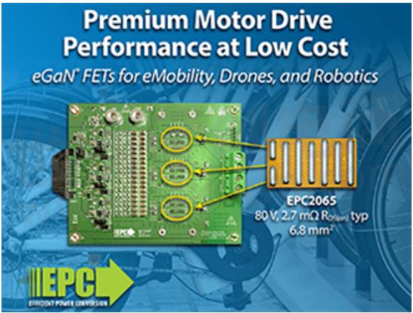
The EPC9167 standard reference design board is a 3-phase BLDC motor drive inverter board featuring the EPC2065 eGaN FET rated at 3.6mΩ maximum RDS(on), 80V maximum device voltage. This standard configuration uses single FETs for each switch position and can deliver up to 20 ARMS maximum output current.
A high current configuration, the EPC9167HC, version of the reference design uses two paralleled FETs per switch position with the ability to deliver up to 42 Apk (30 ARMS) maximum output current.
Both versions of the EPC9167 contain all the necessary critical function circuits to support a complete motor drive inverter including gate drivers, regulated auxiliary power rails for housekeeping supplies, voltage, and temperature sense, accurate current sense, and protection functions. The boards also feature the ST Microelectronics, STDRIVEG600, smart motor drive GaN half-bridge driver.
The EPC9167 boards measure just 130mm x 100mm (including connector). The boards can also be configured for multiphase DC–DC conversion and support both phase and leg shunt current sensing.
Major benefits of a GaN-based motor drive are exhibited with these reference design boards, including lower distortion for lower acoustic noise, lower current ripple for reduced magnetic loss, lower torque ripple for improved precision, and lower filtering for lower cost. The EPC9167 boards' lower weight and size enable incorporation of the drive into the motor housing and supports low inductance, higher power density motors.
EPC provides full demonstration kits, which include interface boards that connect the inverter board to the controller board development tool for fast prototyping that reduce design cycle times.
The default setting for the GaN-based motor drive kit is 100kHz switching frequency and 14ns deadtime. While the kit is designed to be programmed for different frequencies and deadtimes, operation at high frequency around 100kHz allows for the elimination of electrolytic capacitors and the use of lower capacitance, and reduce the motor losses. Operating the boards with very small low deadtime of around 14ns allows higher torque per ampere. The joint effect is to improve inverter and motor system efficiency of more than 7% vs. a silicon MOSFET solution which typically operates at 20kHz and 500ns deadtime.
"GaN-based inverters increase motor efficiency while reducing their cost and delivering the same performance as an expensive motor using a silicon MOSFET-based inverter", said Alex Lidow, CEO of EPC. “This enables motor systems that are smaller, lighter, less noisy, have more torque, more range, and greater precision.”
- 【Datasheet】Enhancement-Mode Gallium Nitride Technology
- 【Datasheet】Enhancement-Mode Gallium Nitride Technology
- 【Datasheet】EPC2065 – Enhancement Mode Power Transistor
- 【Datasheet】Enhancement-Mode Gallium Nitride Technology
- +1 Like
- Add to Favorites
Recommend
- EPC Introduces EPC9157 48V to 12V Demo Board Featuring EPC eGaN FETs and New Renesas DC-DC Controller
- EPC‘s New EPC9165 Bidirectional Converter that Delivers 2kW with 96.8% Peak Efficiency
- Design High-Performance Class-D Audio Amplifiers with EPC’s New Reference Design EPC9192 and eGaN FETs
- Sharge Selects GaN FETs EPC2218 from EPC for High-power USB PD Charger Retro 67 to Achieve the Most Efficient Power Conversion
- EPC Announces EPC9193 eGaN® FET Based 3-Phase BLDC Motor Drive Inverter for Low-Cost E-Bikes, Drones and Robotics
- EPC Launches a 3-phase BLDC Motor Drive Inverter EPC9173 with Embedded Gate Driver Function and a Floating Power GaN FET with 3.3mΩ RDS(on)
- Sekorm Became an Authorized Distributor of EPC(Efficient Power Conversion), Which Brings GaN FET Products
- EPC GaN FETs Enable 75 - 231Ampere Laser Diode Control in Nanoseconds for Advanced Automotive Autonomy
This document is provided by Sekorm Platform for VIP exclusive service. The copyright is owned by Sekorm. Without authorization, any medias, websites or individual are not allowed to reprint. When authorizing the reprint, the link of www.sekorm.com must be indicated.
Integrated Circuits


Discrete Components


Connectors & Structural Components


Assembly UnitModules & Accessories


Power Supplies & Power Modules


Electronic Materials


Instrumentation & Test Kit


Electrical Tools & Materials


Mechatronics


Processing & Customization


