Microstrip Isolator/Circulator Mounting Instruction Manual

In this article, UIY will share the mounting instruction manual for the Microstrip Isolator/Microstrip Circulator.
Storage Conditions:
This product must be stored in a cool and dry area. (Nitrogen Cabinet or Dry Cabinet)
Operation:
Operating with a Plastic or Bamboo Tweezer and Free-Dust Finger Cots on a clean area.
Avoid scratching on the Microstrip Line.
Cleaning Process:
It is recommended to use Absolute Ethanol to clean the surface or wipe gently with Anhydrous Ethanol Cotton.
CAUTION! DO NOT WASH IN AN ULTRASONIC CLEANER!
Mounting Instruction:
Welding Process:
Solder with a melting point of 183℃ or below is recommended for installation, for example, Sn63pb37 Solder Paste or Solder sheet.
If using a Heating Platform for welding, remove the products after the solder is fully melted at 200℃, and the residence time does not exceed 30 seconds.
Bonding Process:
The Dots of conductive glue should be even and uniform. After the product is placed in the installation position and pressed tightly, the conductive glue can be seen around it but not exceeds. The curing temperature is less than 140℃.
Lead Connection:
Bonding Method:
The bonding gold wire is recommended to be 25μm, the thermosonic bonding temperature is 100-150℃, the pressure of the ball bond is 30-55gf, and the pressure of the wedge bond is 15-25gf.
Soldering Method:
Place the box/board with the microstrip product installed on a 120℃ heating table to preheat.
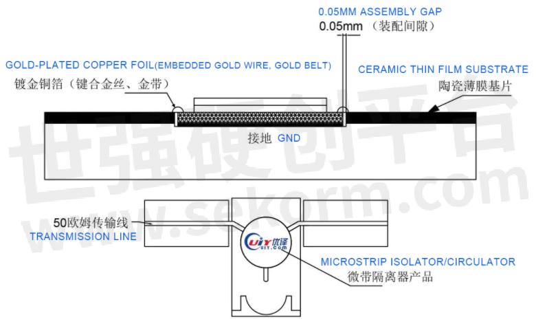
It is recommended to use solder with a melting point temperature of 183℃ or below, and then lap the gold-plated copper foil connecting wires pre-pressed into a certain arc to the flux-coated on the microstrip line, use a pointed electric soldering iron to solder the connecting wires in sequence.
The temperature of the soldering iron is set at 210-230℃, and the soldering time does not exceed 2 seconds per time.
It is required that the soldering should be as little as possible and the solder joints should be smooth and round.
Soldering of leads is generally not recommended.
Assembly Instruction Chart:
[1] Mounting Gap for Assembly Dimensions:
![]()
[2] The unilateral assembly gap of the product should be <0.05mm

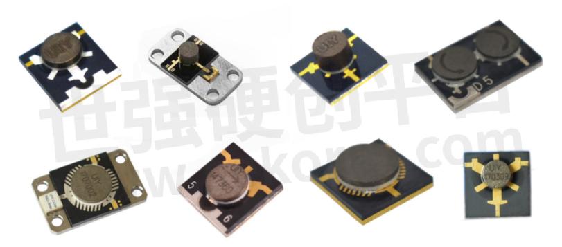
Microstrip Isolator/Circulator Images

- +1 Like
- Add to Favorites
Recommend
- The Anatomy of a Microstrip Isolator and Circulator: Understanding the Basics of Microwave Microstrip Isolator and Circulator Technologies
- High Performance Microstrip Circulators Embedded into The Active Antenna Transmitter/receiver Modules for Thales Alenia Space
- Knowles‘ Microstrip Filters Offer a High Repeatability and Temperature Stability from -55℃ to 125℃
- Knowles Microstrip Filter Helps Your Thin Film RF Devices to Achieve the Best Performance
- Smiths Interconnect’s Isolator is Connecting with (Potential) Life on Jupiter’s Moons
- X-band RF Isolator and Circulator
- Kinghelm‘s Micro-B Female USB Connector KH-MICRO-SMT.J7.2-5P with Current Rating of 1A Max
- Installation of UIY Surface Mounting Isolator/Circulator
This document is provided by Sekorm Platform for VIP exclusive service. The copyright is owned by Sekorm. Without authorization, any medias, websites or individual are not allowed to reprint. When authorizing the reprint, the link of www.sekorm.com must be indicated.


