The Anatomy of a Microstrip Isolator and Circulator: Understanding the Basics of Microwave Microstrip Isolator and Circulator Technologies
Microstrip isolators and circulators are broadband structures which offer a unique blend of broadband operation, low mass & low profile which together make them ideal for use in active electronic arrays used in communication and radar systems in terrestrial and space applications.
A microstrip circulator is generally a passive, non-reciprocal three-port device that only allows a microwave or radio-frequency signal to exit through the port directly after the one it entered. An isolator is a two-port device that transmits microwave or radio frequency power in one direction only, while the other direction is blocked. Isolators can be considered as a special case of a circulator and are made by terminating one port of the circulator ports with a suitable load.
Microstrip devices are normally used in hybrid constructions with wire bonding used to integrate the device into the circuit. Other types that are suitable for low temperature solders are becoming increasingly popular.
Applications are dominated by products whose small physical size and low mass are particularly valued. For example, typically a 30GHz isolator would have a 4x4mm footprint and have a mass of <0.2g, while an X-Band circulator would have a 7x7mm footprint and weigh <0.4g.
Microstrip isolators and circulators are comprised of up to 9 individual material layers, each material selected for its electro-magnetic and thermo-mechanical properties. These layers are assembled by bonding the layers to form a sandwich construction using a variety of specialist epoxies and processes which are processed using precisely applied mechanical pressure during carefully controlled thermal profiles.
Independent of operating parameters all devices are made using the same basic materials and assembled using broadly common processes. Isolator and circulators operate over assigned frequency bands, with typically 20-25% fractional bandwidths. The operating frequency, temperature and RF power dictates the design approach and heavily influences the choice of ferrite and magnetic material.
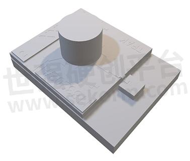
A typical isolator construction is illustrated in the following simplified diagram with each of the major components described below.
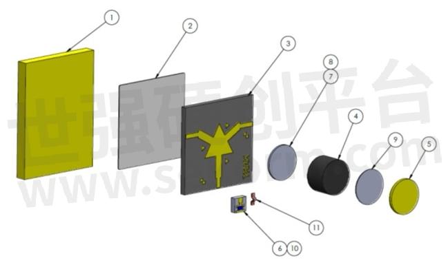
1. The carrier: serves two important purposes, to provide structure to the relatively brittle ferrite material and to provide a return path for the magnetic field created by the magnet. Carriers are usually made from a specialist grade of steel with the precise choice being influenced by several factors including their thermal, magnetic and mechanical properties. Where the isolator operates over narrow temperature excursions the carrier can be made from lower cost mild steel and in for specialist applications non-ferrous materials are occasionally employed. Carriers are usually plated with Ag or Au to prevent corrosion.
2. The epoxy layer (item 3) is used to bond the carrier to the patterned ferrite tile. The epoxy is either a conductive preform or occasionally a liquid conductive type. The bonding of these two parts is a crucial process and one that must ensure that the carrier and substrate surfaces are parallel to each other, precisely aligned and so that bond line is free from voids and with a visible but negative meniscus. This process also sets the bond height: the distance between the ground onto which the microstrip is mounted by the user and the surface onto which the user bond the part into their circuits.
3. The substrate: is made from ferrite selected based on the frequency, magnetic, RF power handling characteristics and mechanical compatibility with the carrier. The ferrite is patterned onto larger tiles and then singulated into individual patterned parts. This processing step is highly specialized and the details of the materials used and the process itself jealously guarded! The ferrite thickness and the pattern itself is based on the design operating parameters. If the device features grounding vias then these are included as part of the ferrite patterning process.
4. The magnet’s purpose is to provide the field that biases the ferrite. The magnet size and type are dependent on many complex design considerations with the expectation that the magnet’s strength tracks the ferrite materials’ variation as a function of temperature. The magnet in combination with the carrier is designed so the bias is optimised over as wide a temperature range as possible. The position of the magnet with respect to the etched Au pattern is crucial to the electrical performance.
5. In some cases a pole piece or label (5) is attached to the magnet. A pole piece acts to reduce (not eliminate) the stray magnetic field and is made from steel and attached to the magnet with epoxy (9). Where a pole piece is employed this offers a convenient surface on which the device serial number and other relevant information can be machine or laser etched. Where stray magnetic fields are not important a lower cost label made from Aluminum can be use. Adding a pole piece or label does have cost implications and their inclusion or not decided prior to the design being completed.
6. Were this a circulator the device would be complete. In this case it is an isolator and a chip termination (6) attached to the carrier (grounded for electrical and thermal reasons) using epoxy with the live pad attached the substrate using Au tape (11) to provide the load. There are several methods of terminating a circulator with the chip termination having the advantages of providing a bulk absorber capable of handling several Watts of RF power while offering a 50Ohm resistance bleed path.
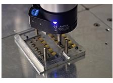
Smiths Interconnect has produced almost 700,000 microstrip isolators and circulators over the past 2 decades from 300 portfolio products. The innovation continues and on average 12 new designs being added to the portfolio each year. Today automation is used to produce a large proportion of the devices supplied with robot assembly working had in hand with human operators to bring unheard of device consistency and quality.
Microstrip isolators and circulators are broadband structures offer a unique blend of broad band operation, low mass & low profile which together make them ideal for use in hybrids for space and terrestrial AESA applications.
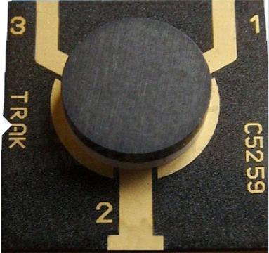
The device in the image above is a microstrip circulator. The three ports are arranged in the “Y” configuration favored by most Transmit/Receive module designers with the common or antenna port opposite the Tx and Rx ports. This particular device operates in C-Band (5.2-5.9GHz) and is available in a variety of types including versions with co-planar waveguide (ground-signal-ground) interfaces. This device has been used in both defence and commercial space-based radar systems and is designed to operate at 50W.
Potential customers interested in knowing more about this and related capabilities may contact Smiths Interconnect and discuss their specific needs. Our experienced technical staff will be pleased to detail the potential performances, mechanical details, and share the fruits of Smiths Interconnect’s 20 years of experience designing and producing these types of devices.
Smiths Interconnect has a large portfolio of existing microstrip isolators and circulators designed to operate in assigned bands from 2.0 to 32.0GHz at operating powers that extend to 100Wpk in X-Band with each device resulting from the same rigorous design and manufacturing process. In addition to microstrip Smiths Interconnect has a range of SMT devices developed primarily for radar applications in L, S, C & X-bands and a broader range of passive products intended for civilian, defence and space applications using a variety of interfaces including MIC, stripline and waveguide and which have resulted from 4 decades of investment and hard-won experience.
- +1 Like
- Add to Favorites
Recommend
This document is provided by Sekorm Platform for VIP exclusive service. The copyright is owned by Sekorm. Without authorization, any medias, websites or individual are not allowed to reprint. When authorizing the reprint, the link of www.sekorm.com must be indicated.
Integrated Circuits


Discrete Components


Connectors & Structural Components


Assembly UnitModules & Accessories


Power Supplies & Power Modules


Electronic Materials


Instrumentation & Test Kit


Electrical Tools & Materials


Mechatronics


Processing & Customization


