What Is a DC/DC Converter? Part 5

Introduction
Hello, everyone. This is the final volume about DC/DC Converters. I have explained the basic operations and features to understand DC/DC converters over the past four volumes because there are various control methods and types of DC/DC converters. In this final volume, I would like to briefly organize those contents to review. I will also introduce different types of DC/DC converters from those I have explained so far.
Contents
Overview of DC/DC Converters
Charge Pump
Conclusion
Overview of DC/DC Converters
DC/DC converters are devices that convert a DC voltage to another DC voltage. Linear Regulators are also classified into the category of DC/DC converters. The term "DC/DC converter", however, is used exclusively to refer to switching regulators in this course.
(1) Basic Operation and Efficiency of DC/DC Converters Compared to Linear Regulators
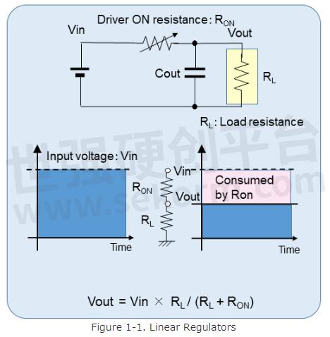
The linear regulator consumes extra power from the input supply by dissipating it as heat in the output driver and provides the voltage and the current required by the load. This is shown in Figure 1-1.
In contrast, buck DC/DC converters divide the energy supplied by the input power supply into time pulses of a ratio corresponding to the energy required by the output and supply the voltage and the current required by output loads by smoothing these pulses. This ideally achieves 100% efficiency. This is shown in Figure 1-2.
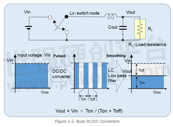
At this time, an inductor along with an output capacitor forms low-pass filters to smooth the pulse train and convert it to the voltage required by the load. The inductor, furthermore, plays an even more important role. The inductor supplies a current to the load and stores the energy from that current when it is connected to the input power supply. When the inductor is disconnected from the input power supply and connected to the GND, it plays a role in supplying current to the load from the GND by releasing its energy.
(2) Time Ratio Control (PWM control and VFM (PFM) control)
DC/DC converters divide the energy supplied from the input power supply into time pulses of a ratio corresponding to the energy required by the output and smooth these pulses. In other words, the input voltage is converted to the required voltage by controlling the time ratio. There are two types of ratio control methods: PWM control and VFM (PFM) control.
PWM Control
PWM control is constant operating frequency and controls the Ton time of a constant period, which is called duty, where Ton is the on time in one cycle.
If the load current is large and a non-zero inductor current flows continuously, the output voltage is not dependent on the load current but is defined as the value calculated by the input voltage and the duty. Constant frequency and continuous operation may make the efficiency worse at light load, however, it is easy to suppress noise because of constant frequency.
Even in PWM, nonsynchronous (diode) rectification, or synchronous rectification with reverse current protection, which are described in the next section, discontinuous inductor current occurs when the load current decreases. In this operation, the duty is increased or decreased according to the load current to keep the output voltage constant.
VFM (PFM) Control
This method controls the switching period (pulse interval) according to the load current with a constant pulse time of Ton. When the load current decreases, the switching frequency also decreases accordingly, and the power consumption of the control circuit decreases. As a result, high efficiency at light load is maintained. However, it is difficult to take a countermeasure against noise because the switching noise frequency spreads to the low-frequency side.
(3) Rectification Method
DC/DC converters divide the energy supplied by the input power supply into time pulses of a ratio corresponding to the energy required by the output, and then smooth the pulses and supply them to the output load.
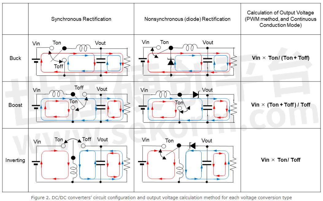
In other words, the input DC power supply is once converted to pulses and then rectified to extract DC voltage. There are two types of rectification methods used in the process: a synchronous rectification method and a nonsynchronous (diode) rectification method.
Both synchronous and nonsynchronous (diode) rectifications have the same configuration of switches that connect the input power supply with the inductor to accumulate energy, but the configuration that is used for releasing the inductors’ energy is different. Nonsynchronous rectification uses a diode, while synchronous rectification uses a switch.
1. Forced PWM and Normal PWM Synchronous Rectification
In forced PWM synchronous rectification, the switch allows current to flow in reverse, the continuous current operation can be maintained even at light loads, and there is no high-frequency noise generation like in the nonsynchronous (diode) rectification method. In Normal PWM synchronous rectification, the reverse current protection function allows operation equivalent to that of nonsynchronous rectification. Moreover, there is no loss of efficiency due to the forward voltage of the diode by using a switch instead of a diode.
2. Nonsynchronous (Diode) Rectification
To reduce the efficiency loss due to the forward voltage of a diode, a Schottky barrier diode with a low forward voltage is usually used as an external component. If the load current is low, the switching node becomes high impedance and the inductor current becomes zero, resulting in discontinuous current operation, which causes high-frequency oscillation (ringing) at the switch node and causes noise.
(4) Types of Voltage Conversion
Linear regulators can only perform buck operation, which means generating a voltage lower than an input supply voltage. DC/DC converters can operate not only as a buck but also as a boost or an inverted voltage converters from the input voltage by changing the circuit configuration of an inductor, capacitors, and switches.
For each of the two types of rectification methods described above, the calculation formulas of the output voltage are listed in the table for each voltage conversion type, as well as circuit configurations.
* From here, I will explain about DC/DC converters that have not been mentioned so far.
(5) Isolated, non-isolated DC/DC converters
There are two classifications of DC/DC converters: isolated and non-isolated. The DC/DC converters I have explained so far are non-isolated types. The difference between isolated and non-isolated types is explained in the chapter of "DC/DC Converters of Isolated Type" below.
(6) DC/DC Converters without Using Inductors
The DC/DC converters I have explained so far are voltage conversion methods using storing and releasing of energy into and out of an inductor. There is another method called a charge pump circuit that does not use an inductor. This is also explained in the following chapter of "Charge Pump."
Isolated DC/DC Converters
All the DC/DC converters described so far are classified as non-isolated DC/DC converters because they share a common GND between the input power supply side and the output side, and the input side and the output side are electrically connected. Typically, electrical equipment is powered by commercial AC power. Inside equipment, this is converted to the voltage required for the equipment to perform its function. To ensure safety, such as preventing electric shock to the user of the equipment during voltage conversion, voltage conversion using an isolated method is required. Therefore, a transformer is used in which the input side and the output side are electrically completely isolated from each other.
As an example of an isolated DC/DC converter, I would like to introduce flyback converters, which are equivalent in operation to boost DC/DC converters.
Transformers
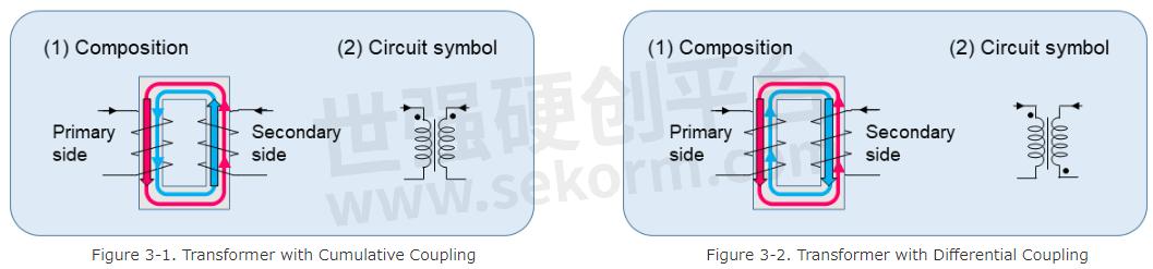
As shown in Figure 3-1 and Figure 3-2, the structure of a transformer consists of two different inductors which are wound on the left side and the right side of a "square" shaped iron core (core). There are two types of transformers depending on how these two relative inductors are wound. One is a transformer with cumulative coupling, and the other is a transformer with differential coupling.
Figure 3-1(1) shows a transformer with cumulative coupling. When a current flows through the left inductor from above in the direction indicated by the black arrow in the figure, magnetic flux is generated in the left inductor in a downward direction according to the right-hand screw rule. At the same time, upward magnetic flux is generated in the right inductor through the iron core. On the other hand, when the inductor current flows through the right inductor from above in the direction indicated by the black arrow in the figure, upward magnetic flux is generated in the right inductor, and downward magnetic flux is generated in the left inductor through an iron core at the same time. This is called cumulative coupling because the two inductors strengthen each other's magnetic flux. As shown in Figure 3-1(2), to indicate a transformer with cumulative coupling in the circuit symbol, two dots (●) are marked in the same direction on the left and right inductors in the circuit symbol.
On the other side, Figure 3-2(1) is a transformer with differential coupling. Compared to Figure 3-1(1), the winding direction of the inductor on the right side is reversed. In this case, because the two inductors weaken each other's magnetic flux, it is called a transformer with differential coupling. In the circuit symbol, two dots (●) are marked in opposite directions on the left and right inductors. In isolated DC/DC converters, the use of either transformer depends on the type of converter, so the two types must be clearly distinguished.
As shown in Figure 4-1, the circuit is configured using a transformer with differential coupling where the primary side is on the left side of the transformer and the secondary side is on the right side. This is an isolated flyback converter. Let me provide an overview of the flyback converter operation using Figure 4-1 through Figure 4-3.
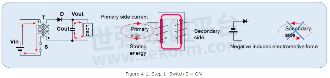
Step 1: As shown in Figure 4-1, when switch S turns on, downward magnetic flux in the primary inductor and upward magnetic flux in the secondary inductor connected by an iron core begin to increase. According to Lenz's law, a negative induced electromotive force is generated in the secondary inductor. However, there is no transfer of energy from the primary to the secondary because the diode is reverse-biased and does not flow a current. This means that the primary inductor current is used only to store energy in the primary inductor.
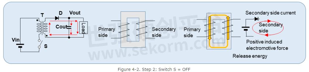
Step 2: As shown in Figure 4-2, when switch S turns off, the inductor current is cut off in the primary inductor, so downward magnetic flux changes to zero, and upward magnetic flux in the secondary inductor connected by an iron core also changes to zero at the same time. According to Lenz's law, a positive induced electromotive force is generated in the secondary inductor. Because the diode is forward-biased at this time, a current is supplied to the output capacitor, Cout, and the loads.
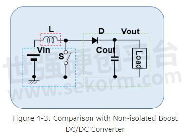
All the energy stored in the transformer by the current of the primary side when switch S turns on is released as current to the secondary side when switch S turns off. Although the input and output sides of the flyback converter are isolated by a transformer, flyback converters are operating just like boost DC/DC converters shown in Figure 4-3.
Charge Pump
Inductive DC/DC converters can generate stable voltage with high efficiency by controlling the time ratio of storing and releasing in the form of magnetic energy to the inductor. A boost, buck, or inverted voltage can be generated by changing the circuit configurations of the input power supply, a rectifier element, switches, and an inductor.
Inductors are not only devices that can store and release energy. Capacitors can also store and release energy in the form of charge and DC/DC converters can be realized without using inductors. This is called a charge pump circuit.
Principle of charge pump operation
A charge pump circuit charges one or more capacitors from the input power supply and can generate a boost, buck, or inverted voltage concerning the input voltage by changing the connections of these capacitors with switches.
Figure 5-1 through Figure 5-3 illustrates the principle of charge pump operation.
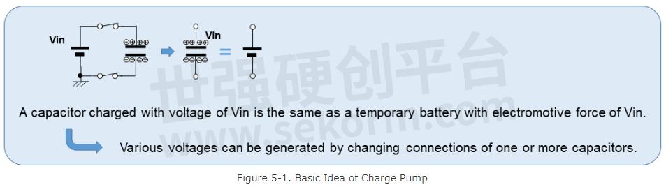
As shown in Figure 5-1, a capacitor charged by the input power supply performs as a temporary battery. This capacitor is called a flying capacitor. Considering a capacitor as a battery, it is easy to imagine that various voltages can be generated by changing the connections of this battery. Figure 5-2 shows the concept of buck, boost, and inverting voltage generations by a charge pump.
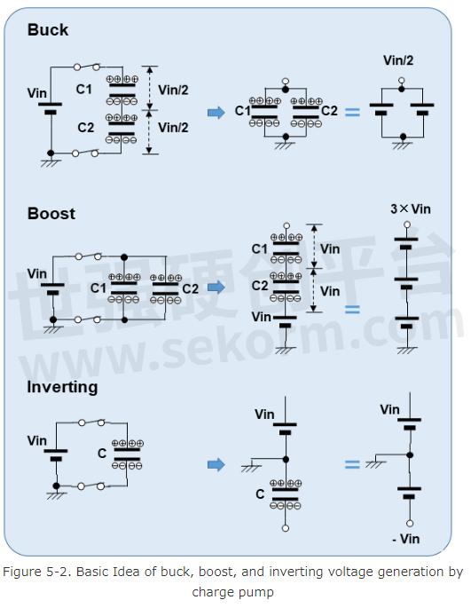
Buck
If capacitors C1 and C2 of the same capacitance are connected in series and charged with Vin, the voltage across each capacitor is Vin / 2. If the capacitors are connected in parallel, the temporary battery with a voltage of Vin / 2 is realized. This is the principle of a buck operation with a charge pump.
Boost
Capacitors C1 and C2 of the same capacitance are connected in parallel and charged with Vin. If the capacitors are connected in series and connecting the negative side to the positive (+) side of Vin, a temporary battery with a voltage of 3 × Vin is realized. This is the principle of a boost operation with a charge pump.
Inverting
A capacitor charged with Vin has a polarity similar to that of a usual battery. Just as connecting the positive (+) side of a battery to GND = 0V produces a negative voltage of −Vin, connecting the positive (+) side of a capacitor charged with Vin to GND = 0V produces a negative power supply with the voltage of −Vin at negative (−) charged side of a capacitor. This is the principle of an inverting operation with a charge pump.
Then, how is the actual charge pump controlled? I explain a double voltage charge pump as the simplest example as shown in Figure 5-3.
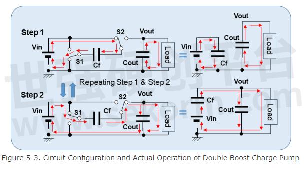
Step 1: The flying capacitor, Cf, is charged with Vin by connecting switch S1 to the GND side and switch S2 to the Vin side. The smoothing capacitor for voltage hold, Cout, supplies double the voltage of Vin and the current required by the loads.
Step 2: Cout is charged with double the voltage of Vin by connecting switch S1 to the Vin side and switch S2 to the Vout side. It supplies double the voltage of Vin and the current required by the loads.
A stable voltage and current can be generated by alternately repeating Step 1 and Step 2.
Features of Charge Pump DC/DC Converters.
As shown in Figure 5-1 through Figure 5-3, the principle of operation is very simple, and the design is extremely easy. As readers who have been reading our series of articles may have already noticed, there is no need for a phase design to achieve stable operation because there is no feedback control to make the voltage constant like in linear regulators and DC/DC converters.
Like a DC/DC converter, it can generate buck, boost, and invert voltages. The only external components are the output capacitor, Cout, and one or more flying capacitors, Cf.
However, as shown in Figure 5-1 through Figure 5-3, the flying capacitor, which serves as a temporary battery, is charged by the input power supply Vin, so the voltage of the temporary battery is the voltage of Vin or about 1/2, 1/3, and 1/4 of that voltage. Therefore, the steps of output voltage are coarse, and the fine adjustment is difficult. The output voltage also fluctuates in proportion to the input voltage. It is not used for applications that require high accuracy. The output current is also limited by the capacitance of the flying capacitor. Not only that, the output current can only be supplied from the output capacitor when the flying capacitor is charged, the ripple voltage increases when the load current is large. For these reasons, it is not suitable for applications requiring high current.
Conclusion
In these five volumes on DC/DC converters, I have mainly taken non-isolated DC/DC converters as examples, and only the basics of the converters have been mentioned. As for isolated DC/DC converters, I have only explained flyback converter as an example. I would say that we are just getting to know about the fundamental concepts of DC/DC converters.
This course is intended as an entry level course of DC/DC converters and this marks the end of this course.
So far, I have explained linear regulators and DC/DC converters (switching regulators) as power management ICs that supply the voltage and current required by each device from the input power supply. For these power management ICs to operate properly, an appropriate voltage must be supplied from the input power supply and the power management ICs themselves must operate as expected. Therefore, it is necessary to monitor whether these power supplies are operating properly.
Thank you very much for reading.
- +1 Like
- Add to Favorites
Recommend
- P-DUKE Releases EN 50155 Approved Compact 1”x1” 10W DC/DC Converter with Patented Enhanced Hold-up Function
- What Is a DC/DC Converter? Part 2
- What Is a DC/DC Converter? Part 1
- What Is a DC/DC Converter? Part 4
- What Is a DC/DC Converter? Part 3
- 20W Railway approved DC/DC Converter with patented Hold-up Function
- New 2W medical grade DC/DC converter in a compact SIP-8 package
- Nisshinbo Launched Development of First MUSES-Series High-sound-quality Power Management IC
This document is provided by Sekorm Platform for VIP exclusive service. The copyright is owned by Sekorm. Without authorization, any medias, websites or individual are not allowed to reprint. When authorizing the reprint, the link of www.sekorm.com must be indicated.
Integrated Circuits


Discrete Components


Connectors & Structural Components


Assembly UnitModules & Accessories


Power Supplies & Power Modules


Electronic Materials


Instrumentation & Test Kit


Electrical Tools & Materials


Mechatronics


Processing & Customization


