What Is a DC/DC Converter? Part 1

Now let me introduce another important power management IC type, DC/DC Converters (switching regulators). In this section, let's focus on the buck (step down) DC/DC converters, and I will explain how it generates constant output voltage compared to Linear regulators' operation.
*The terms switching regulators and step down will be omitted hereafter.
Contents
Review of Linear Regulators
Buck DC/DC Converter’s Voltage Generation Method
Conclusion
Buck DC/DC Converters
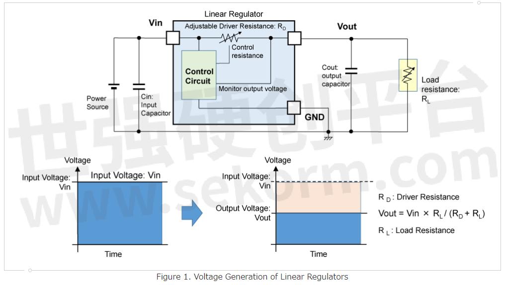
Figure 1 shows a basic circuit and an image of linear regulators' operation. Figures 2 and 3 show a basic circuit and an image of buck DC/DC converters' operation.
Review of Linear Regulators
Before talking about DC/DC converters, please remember how linear regulators work. A linear regulator has an internal driver behaving as an adjustable resistor, and a stable output voltage can be generated by adjusting driver resistance (RD) depending on the load resistance (RL).
Example: Vin = 5V, Vout =2V, Iout = 100 mA
Load resistance (RL) = 2V / 0.1 A = 20ohms
Linear regulators adjust the internal driver's on resistance to 30 ohms.
RD = 30 ohms and RL = 20 ohms will form divider resistors to output 2 V from 5 V.
Therefore, the output voltage of linear regulator, Vout, is expressed as the voltage division of input voltage, Vin, by the ratio of these resistors:
Vout = Vin × (RL / (RD + RL)).
Fluctuation of Load Resistance (Load Current)
If RL changes from 20 ohms to 10 ohms slowly, linear regulators change RD from 30 ohms to 15 ohms keeping resistance ratio of RD to RL as 3 to 2. In other words, the resistance ratio is constant regardless of load resistance (load current) value.
Fluctuation of Input Voltage
Let's think about the case when Vin slowly changes from 5 V to 8 V. To generate 2 V from 8 V, resistance ratio, RD:RL needs to be 3 to 1, and RD will change from 15 ohms to 30 ohms.
Thus, a linear regulator generates output voltage 2.0 V by adjusting on resistance of the driver by monitoring the output voltage.
Buck DC/DC Converter’s Voltage Generation Method
A buck DC/DC converter consists of a high-side switch between an input power source and the output and a low-side switch between GND and the output. DC/DC converters switch the high-side switch and the low-side switch alternately with a constant ratio, and the output voltage is generated by smoothing the output pulse waveform by a capacitor (and the inductor) to provide the load current.
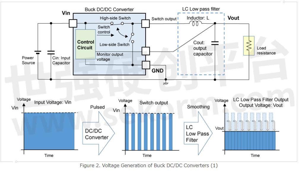
Suppose that the on period of the high-side switch is "Ton," and the off period of the high-side switch is "Toff" (or the on period of the low-side switch), the output voltage which is smoothed by LC filter is determined by the ratio of the Ton to Toff. The ratio of Ton against the whole period is called "duty ratio." By increasing the duty ratio, the output voltage also increases. The output voltage can be expressed as:
Vout = Vin × (Ton / (Ton + Toff)).
These are illustrated in Figure 3.
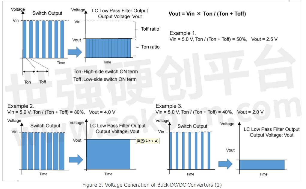
In Figure 3, when Vin = 5.0 V,
Example 1 shows that when duty ratio is 50%, Vout becomes 2.5 V, and
Example 2 shows that when duty ratio is 80%, Vout becomes 4.0 V, and
Example 3 shows that when duty ratio is 40%, Vout becomes 2.0 V.
The time ratio control like this is used for LED dimming control. LED luminance can be controlled with high-speed switching wherein the human eye does not notice any flicker. Our eyes play the role of a low pass filter. We feel LED is bright when LED on time is long. Contrary to that, we feel that it is dark when the LED on time is short.
The explanation above only shows the result that the pulse waveform is smoothed by passing it through an LC low-pass filter and an output voltage corresponding to the time ratio of the pulse waveform is obtained.
The concept of low pass filter might be difficult to grasp. The explanation based on divider resistors of linear regulators may be much easier to understand. Therefore, I will try to make another explanation replacing output voltage control by time ratio of buck DC/DC converters with parallel resistance proportional to time ratio (Ton and Toff) in Figure 4.
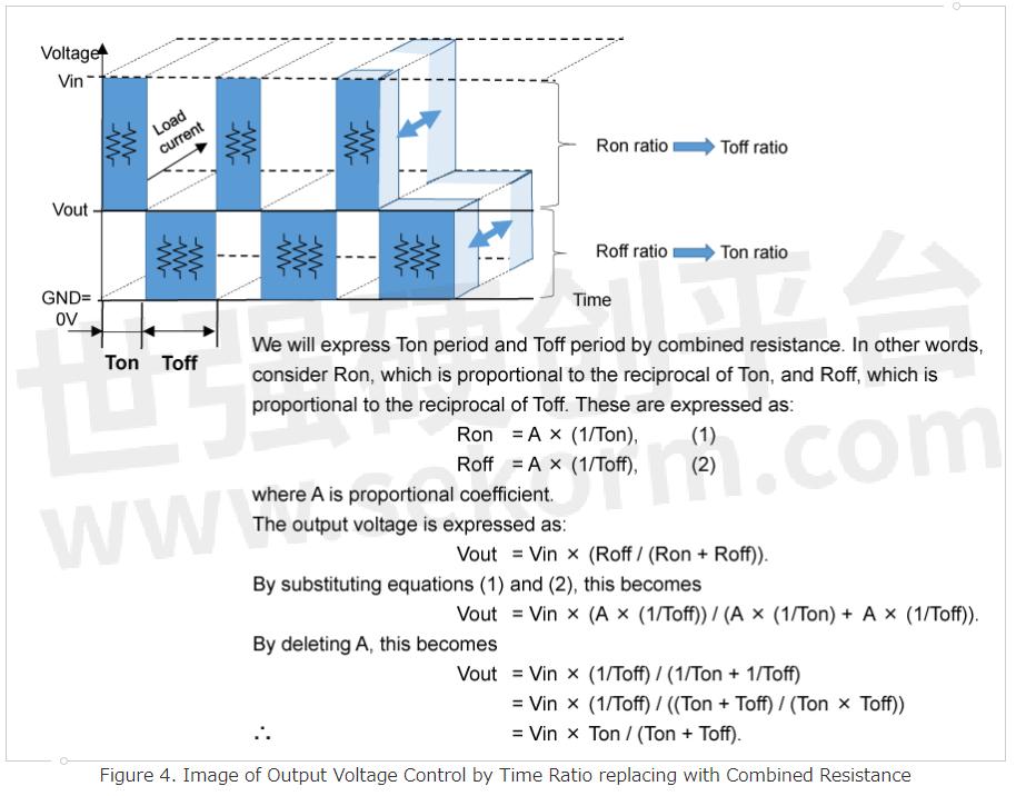
Replacing on time period of the high-side switch between Vin and Vout with parallel resistances, total combined resistance is described as Ron. In the same way, replacing on time period of the low-side switch between Vout and GND with parallel resistances, total combined resistance is described as Roff. According to this, Vout can be expressed as the voltage division of Vin by Ron and Roff.
*I use divider resistors to explain, but please note that it is impossible for high-side and low-side switch to be allowed to turn on at the same time. So, there is no current flow from Vin to GND through Ron and Roff.
Ron is proportional to the reciprocal of Ton, and Roff is proportional to the reciprocal of Toff. Therefore, as shown in Figure 4, Vout is expressed as Vout = Vin × the time ratio of (Ton / (Ton + Toff)).
Linear regulators generate stable output voltage by controlling Ron of internal driver by keeping resistance ratio of RL and RD when Vin is stable and load resistance (load current) fluctuates. On the other hand, output voltage of buck DC/DC converter is decided just by time ratio, and it keeps load current stable. What does this mean? Now, see Figure 5.
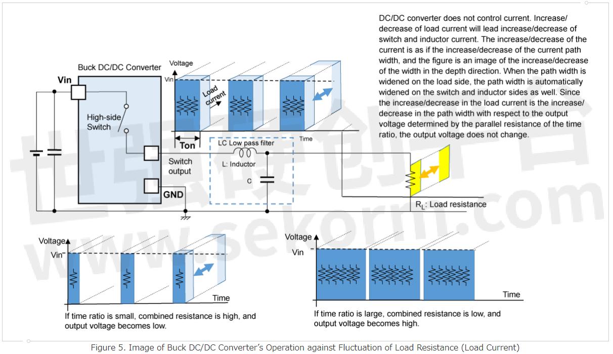
Figure 5 shows an illustration with depth corresponding to the load current. (Figure 4 shows a similar illustration.) Figure 5 shows that increase or decrease in load current increases or decreases this depth but does not affect the time ratio. For example, when load current increases, the depth gets wider like the current path width gets wider. Then current path width of switch and inductor gets wider as well. Therefore, fluctuation of load current has no impact on output voltage or time ratio.
Parallel resistance at low-side is omitted in Figure 5, but please consider it as the same as in Figure 4. I hope the above explanation has given you an idea of what buck DC/DC converters look like.
Fluctuation of Load Resistance (Load Current)
Output voltage of buck DC/DC converters can be expressed as:
Vout = Vin × (Ton / (Ton + Toff)).
Although this formula does not include current, buck DC/DC converters generate stable output voltage even while maintaining a constant duty ratio by changing current path width as described above.
Fluctuation of Input Voltage
Let's think the case that Vin changes from 5 V to 8 V. To generate Vout = 2 V from Vin = 8 V, duty needs to be 25%. Duty will gradually change from 40% to 25% keeping duty ratio = Vout / Vin.
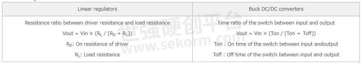
Table 1 shows the comparison chart of voltage generation method of linear regulators and buck DC/DC converters.
Table 1. Voltage Generation Method
Conclusion
This time, we focused on a buck DC/DC converter that can be compared with a linear regulator based on its topology and explained that the voltage generation method is figured as time ratio control. Time ratio control is basic control method for all DC/DC converters. Next time, let me explain the usage of DC/DC converters by comparing them with linear regulators according to their characteristics and properties.
Thank you for reading.
What Is a DC/DC Converter? Part 2, click it.
- +1 Like
- Add to Favorites
Recommend
- What Is a DC/DC Converter? Part 5
- P-DUKE Releases EN 50155 Approved Compact 1”x1” 10W DC/DC Converter with Patented Enhanced Hold-up Function
- What Is a DC/DC Converter? Part 2
- What Is a DC/DC Converter? Part 4
- What Is a DC/DC Converter? Part 3
- 20W Railway approved DC/DC Converter with patented Hold-up Function
- New 2W medical grade DC/DC converter in a compact SIP-8 package
- Nisshinbo Launched Development of First MUSES-Series High-sound-quality Power Management IC
This document is provided by Sekorm Platform for VIP exclusive service. The copyright is owned by Sekorm. Without authorization, any medias, websites or individual are not allowed to reprint. When authorizing the reprint, the link of www.sekorm.com must be indicated.
Integrated Circuits


Discrete Components


Connectors & Structural Components


Assembly UnitModules & Accessories


Power Supplies & Power Modules


Electronic Materials


Instrumentation & Test Kit


Electrical Tools & Materials


Mechatronics


Processing & Customization


