GNSS Modules Command Introduction: “log sysconfig”

“Is there a way to view the current configuration of my module?” Comnavtech met many clients are curious about the current configuration of SinoGNSS K8 OEM board, in today's article, we will introduce the most frequently used information about the system configuration. By command “log sysconfig”, clients can check basic configuration, rtk configuration and work mode like PPS, Event, and SBAS.This command is suitable for most K8-series GNSS modules.
Here shows with ComNav CRU software, to give command “log sysconfig” and its output messages.

1.Basic configuration
In basic configuration, it shows the configuration of calculation rate, satellites cut angle, locked satellites and some other information.
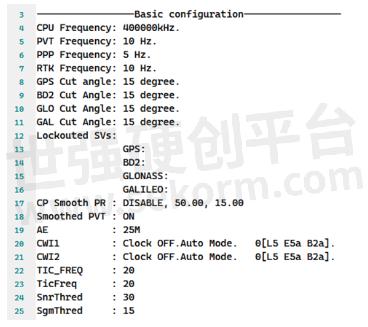
• CPU frequency
In some cases high update rate observation, PVT or RTK is needed, the default CPU core frequency couldn’t bear so huge calculation load, so a high frequency is necessary, at the same time, it means more power cost.
• PVT/PPP/RTK frequency
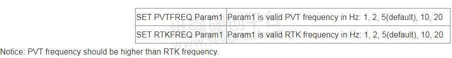
The message refer to PVT/PPP/RTK calculation rate.
In K8 series board, the default settings is 5HZ, if a higher or lower PVT update frequency is needed, this command could configure the PVT update rate at most 20hz.
• GPS/BD2/GLO/GAL cut angle
These message sets the elevation cut-off angle for tracked. The board does not start automatically searching for a satellite until it rises above the cut-off angle. Tracked satellites that fall below the cut-off angle are no longer tracked unless they were manually assigned.

• Lockouted SVs
Prevent the board from using a satellite system. This message prevents the receiver from using satellites in the specified system in the solution computation.
![]()
• CP Smooth PR
A method of combination of CP and PR, to get a higher quality observation.

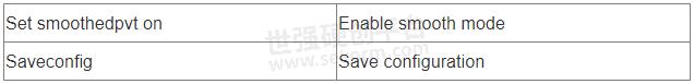
• Smoothed PVT
In single-point positioning, Comnav Technology have adopted an advanced smoothing filter to enhance pass to-pass accuracy, which need send commands as:
• INS Control
The INS (Inertial Navigation System) Mode allows OEM modules to continuously output positioning information through IMU in a short time when losing satellites signal.
ENABLE: INS enabled; DISABLE: INS disabled
1/2/3/4/5/6/7/8: IMU axes type
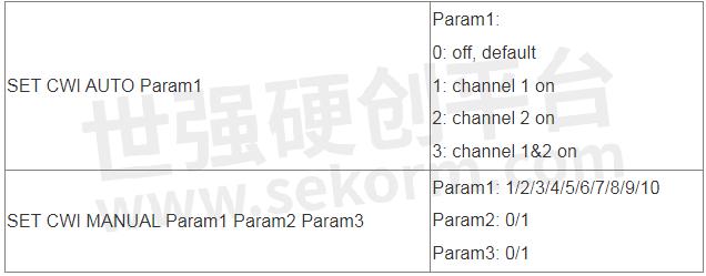
• CWI1/CWI2
K8 OEM modules support two channels to active anti-interference, it refers to CWI1 and CWI2. Clients can enable CWI by auto mode, or manually select the channels. Details can refer to ComNav OEM commands list: CNT-OEM-RM001_Rev_2.3_20220507
2.RTK configuration
This part is the receiver's processing scheme for RTK, and the current working status information.
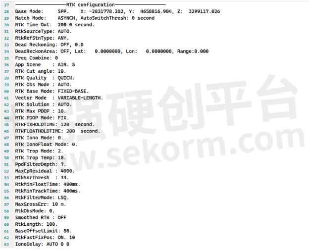
• RTK Time Out
This command is used to set the maximum age of RTK data to use when operating as a rover station. RTK data received that is older than the specified time is ignore.
After rtk disconnects the differential, after 200 seconds, it will exit fixed status.
![]()
• RTKFIXHOLDTIME
This command is used to set the maximum age of RTK fixed data to use when operating as a rover station. RTK fixed data received that is older than the specified time is ignored.

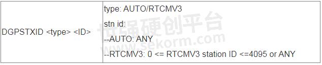
• RtkSourceType
This command is used to identify from which base station to accept RTK differential corrections. This is useful when the receiver is receiving corrections from multiple base stations.

• RtkRefStnType
This command sets the station ID value for the receiver when it is transmitting corrections. This allows for the easy identification of which base station was the source of the data.
• App Scene
This command can be used to set the application mode. In different modes, the RTK engine should process different styles of observation data to improve the performance of the RTK engine.
For example, if you use ComNav K8 series as drone gps module, there will setup APP Scene mode to air.
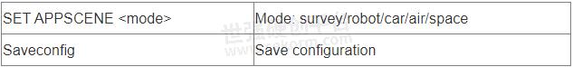
Other options are suggested to keep as default.
3.COM configuration
These message shows the status(normal mode or differential mode) for all COM ports.

4.PPS configuration
PPS, which stands for "Pulse Per Second," is a precise timing signal often used in various applications that require accurate time synchronization.
![]()
With PPS function, you can set the polarity, period and pulse-width of PPS output.
Format: PPSCONTROL <switch> <polarity> <period> <pulse-width>
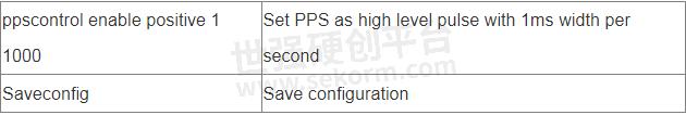
• <switch> supports “enable” or “disable”, notice that “disable” is invalid.
• <polarity> supports “positive” and “negative”, “positive” means high level pulse mode and “negative” means low level pulse mode.
• <period> in seconds, the update rate can be up to 10Hz.
• <pulse-width> in microseconds, pulse-width should be less than half of period.
5.EVENT configuration
Event refers to a significant occurrence, action, or incident that triggers a response or a change in the system's state. Events can be both planned and spontaneous, and they are often used to capture and manage important moments within a system.

Format: MARKCONTROL <signal> <switch> [polarity] [timebias] [timeguard]]
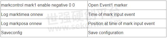
• <signal> supports the key words “mark1” and “mark2”.
• <switch> supports the key words “enable” and “disable”.
• [polarity] supports the key words “positive” and “negative”, which separately represent “positive pulse” and “negative pulse”.
• [timebias] A constant time bias in nanoseconds can be applied to each event pulse. Typically this is used to account for a transmission delay.
• [timeguard] The time guard specifies the minimum number of milliseconds between pulses. This is used to coarsely filter the input pulses.
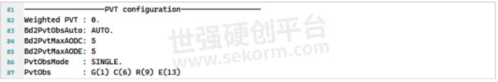
6.PVT configuration
For PVT configuration, parameters normally used for R&D debug.
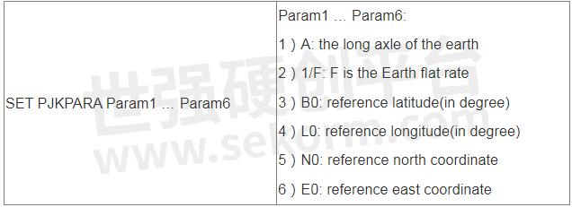
7.Parameter Offset configuration
In this section, it provides parameters for datum and some offset value.
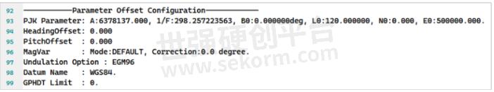
• PJK Parameter: A:6378137.000, 1/F:298.257223563, B0:0.000000deg, L0:120.000000, N0:0.000, E0:500000.000.
• HeadingOffset
This command is used to add an offset in degree in the heading and pitch values of the HEADING, GPHDT, GPNAV, GPTRA, GPYBM and PTNL,AVR logs.
Both heading offset and pitch offset have the default values of 0 degree.

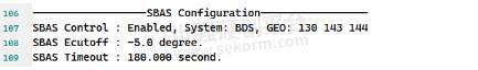
8.SBAS Configuration
SinoGNSS K8-series all support SBAS function.
9.Other Configuration
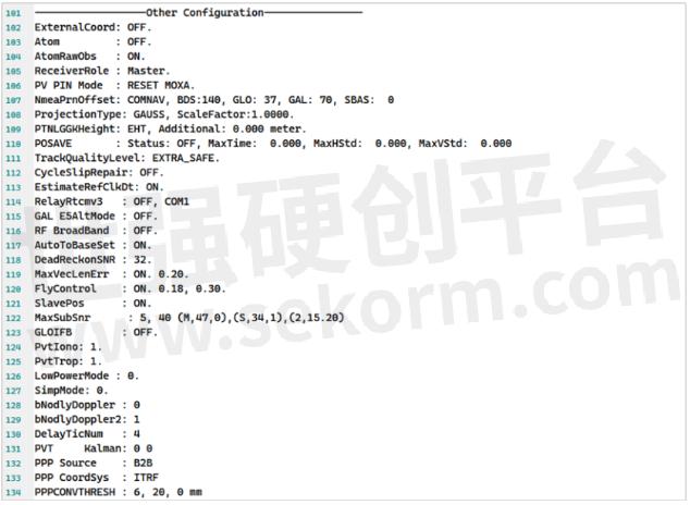
• IMU(INS)
Smoothed DR: OFF // INS smoothing DR TimeOut : 300 // INS hold time
DR InitV: 3.0 // Inertial navigation initialization speed
DR LeverArm: 0.00, 0.00, 0.00 // INS arm value
- +1 Like
- Add to Favorites
Recommend
- The Magic Behind RTK: Delivering Unparalleled Positioning Precision
- Recommend Commands for System Integration
- How to Active the Event Option for Your GNSS Module K8 series from ComNav Technology
- ComNav‘s K8 Series GNSS Module can track the Galileo E6b signal and Has Verified the HAS Service in Most Countries
- Lighter, Thinner, Faster - ComNav Technology Introduced T20 Palm RTK
- How to Enable GNSS+INS System on ComNav K8 Series GNSS Modules
- ComNav Technology Launched GNSS High Precision Positioning Solution for Lawn Mower
- ComNav Technology‘s Z30 Portable GNSS Receiver: Precision in Your Pocket
This document is provided by Sekorm Platform for VIP exclusive service. The copyright is owned by Sekorm. Without authorization, any medias, websites or individual are not allowed to reprint. When authorizing the reprint, the link of www.sekorm.com must be indicated.
Integrated Circuits


Discrete Components


Connectors & Structural Components


Assembly UnitModules & Accessories


Power Supplies & Power Modules


Electronic Materials


Instrumentation & Test Kit


Electrical Tools & Materials


Mechatronics


Processing & Customization


