What Are The Main Parameters Of GDT?

GDT (gas discharge tube) is essentially a discharge gap-sealed in a ceramic cavity filled with inert gas to stabilize the discharge voltage of the discharge tube. Its main features are large flow energy, which can reach tens to hundreds of KA, extremely high insulation resistance, no leakage, no aging failure, non-polarity bidirectional protection, and extremely small static capacitance. It is especially suitable for coarse protection. It can be widely used in the first-level lightning surge protection of various power and signal lines.
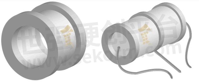
Fig.1
Its Main Parameters Include:
1. Rated Voltage: The working voltage range of the gas discharge tube.
2. Leakage: The leakage current of the GDT gas discharge tube at a fixed voltage.
3. Strike Voltage: The voltage value when the GDT gas discharge tube starts charging and discharging.
4. Protection current: The current value of the gas discharge tube when it is working normally.
5. Time to Protection Current/Voltage: The reaction time under the protection current and voltage that the gas discharge tube can finally start.
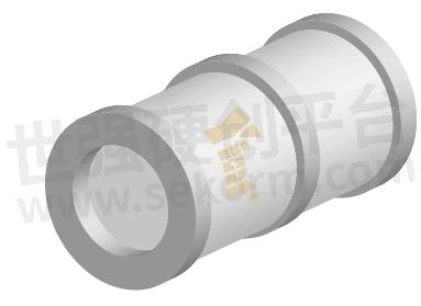
Fig.2
The Following Points Should Be Paid Attention To When Using GDT:
1. The selected GDT gas discharge tube should meet the design requirements and cannot exceed its maximum rated voltage and current.
2. The gas discharge tube is usually installed at the entrance of the circuit to be protected to provide the best circuit protection.
3. After the GDT gas discharge tube is charged and discharged, its internal capacitor will be discharged, which will form an instantaneous high voltage. Therefore, it is necessary to maintain the ground wire and guide wire and avoid direct contact.
4. Do not change the parameters of the gas discharge tube or disassemble and repair it without authorization to avoid electrical hazards.
5. Proper selection and use of GDT gas discharge tubes can greatly improve the withstand voltage level of electronic products, reduce circuit failures, and prolong the service life of electronic products.
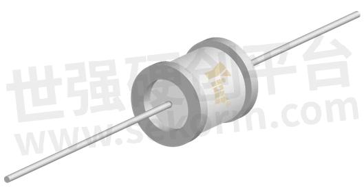
Fig.3
- +1 Like
- Add to Favorites
Recommend
- Yint Electronics‘s MOV, GDT, NTC for AC Line Protection Solution
- Application of Socay GDT Arrester SC3E5-150LSMD in Switching Converter
- YINT‘s Telephone Signal and Other Communication Lightning Protection Solutions
- Gas Discharge Tube SC1812-90CSMD with Small Package Size and Surge Current of 2KA Widely Used in Industrial Field
- Improving Performance of Surge and Lightning Protection Circuits with Current Limiting Devices
- What Protection Devices can be Used to Protect Set-Top Box Protection?
- WAYON High Current Gas Discharge Tubes Features Low Capacitance and Wide Voltage Range, Boosting Circuit Safety Protection
- A 12V DC Lightning Protection Solution from Yint
This document is provided by Sekorm Platform for VIP exclusive service. The copyright is owned by Sekorm. Without authorization, any medias, websites or individual are not allowed to reprint. When authorizing the reprint, the link of www.sekorm.com must be indicated.
Integrated Circuits


Discrete Components


Connectors & Structural Components


Assembly UnitModules & Accessories


Power Supplies & Power Modules


Electronic Materials


Instrumentation & Test Kit


Electrical Tools & Materials


Mechatronics


Processing & Customization


