Annoyed by Failing Noise Immunity Testing after Finishing Board Design?

Have you ever experienced a malfunction due to low noise immunity after developing a new application board? This problem can sometimes happen after passing characteristics tests. Finding the cause of the problem can be very expensive and time consuming. If you are lucky, you could locate and identify the components with the problem and then search for suitable replacement parts. However, it is not always so easy or so simple. In the worst case, you may have to redesign the board which is very costly and time consuming. It is difficult to predict how noise will affect the developing application and adding countermeasures is one of the main factors that lead to increase development time and cost.
Without proper noise immunity, electromagnetic noise can cause abnormal function which may lead to injury or fatal accident especially as electronic devices are increasingly used in cars and industrial equipment. Therefore, it is critical that today's electronic systems take proper precautions to safeguard against unwanted noise.

Importance and Problems on Electromagnetic Susceptibility (EMS)
Everywhere we go, we are surrounded by invisible electromagnetic noise which increases at a high rate with the evolution of electronic devices.
To ensure stable operation of electrical devices under an environment full of electromagnetic noise, there is a growing list of requirements for systems to be equipped with high noise immunity functions. Here are a few examples of common noise immunity requirements: ISO 11452 is an international set of immunity standards and guidelines for automotive electrical components, Transverse Electromagnetic (TEM) call method, and Bulk Current Injection (BCI) method.
If a system cannot pass noise immunity testing, the time and cost would increase due to the need to re-design the circuit and rerouting the wiring patterns of the board.
Incident Cases
There are many cases where manufacturer’s product malfunctioned due to electromagnetic noise and were later required to take corrective action. These cases demonstrate the importance of EMS countermeasures to be as strong and robust as possible and to protect against electromagnetic interference from other devices.
Incident Cases Relating to Electric Wave Announced by Ministry of Internal Affairs and Communications

We have Power Management ICs which achieve high electromagnetic noise immunity. Nisshinbo Micro Devices ICs can provide stable supply voltage under very harsh environment where noise and various frequency are all around.
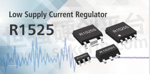
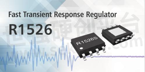
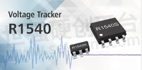
The R1525 series and R1526 series are voltage regulators and the R1540 series is a voltage tracker. All three families are high-noise immunity power management ICs developed using Nisshinbo Micro Devices’proprietary circuit technology. They can supply a stable voltage even under a wide noise frequency condition of 150 kHz to 1 GHz.
The power supply of an off-board sensor system, for example, needs additional components for noise reduction, as electromagnetic noise generated by the wire harness may affect the sensor’s operation. Our "high-noise-immunity power management ICs" eliminate the need for additional components, which reduces mounting area because power management functions and noise suppression functions are all in one chip.
R1540 Circuit Example
Since electrical wires can transmit noise, ICs should have electromagnetic-noise-immunity.

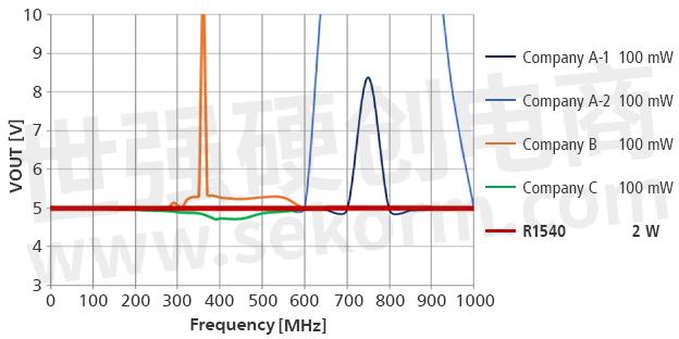
DPI Test Results
There is no visible output voltage fluctuation even after applying 2 W noise!

High Noise Immunity Power Management ICs:

Input Voltage Range (Maximum Rating): 3.5 V to 42 V (50 V)
Output Voltage Range: 1.8 V to 12.0 V
Output Current: 200 mA
Output Voltage Accuracy: ±0.6% (Ta=25℃)
Standby Current: Typ. 0.1 µA
Supply Current: Typ. 2.2 µA (No Load)
Operating Temperature Range: -50℃ to 125℃
Packages: DFN(PLP)1820-6, SOT-23-5,SOT-89-5, HSOP-6J, HSOP-8E

Input Voltage Range (Maximum Rating): 3.5 V to 42 V (50 V)
Output Voltage Range: 1.8 V to 9.0 V
Output Current: 300 mA
Output Voltage Accuracy: ±0.6% (Ta=25℃)
Standby Current: Typ. 0.1 µA
Supply Current: Typ. 32 µA (No Load)
Operating Temperature Range: -40℃ to 125℃
Package: HSOP-8E

Input Voltage Range (Maximum Rating): 3.5 V to 42 V (50 V)
Output Voltage Range: 2.2 V to 14.0 V (Tracking Voltage)
Output Current: 70 mA
Output Voltage Accuracy: ±15mV (All Temp.)
Standby Current: Typ. 0.1 µA
Supply Current: Typ. 60 µA (No Load)
Operating Temperature Range: -40℃ to 125℃
Packages: SOT-23-5, HSOP-8E
About Nisshinbo
New Japan Radio Co., Ltd. and Ricoh Electronic Devices Co., Ltd. of the Nisshinbo Group were integrated and started operation as Nisshinbo Micro Devices Inc. in January 2022. Nisshinbo integrated the strengths of both companies and refine "Connect Everything" technology, and, therefore, strive for further growth and development as an "Analog Solution Provider toward the realization of an ultra-smart society.
- +1 Like
- Add to Favorites
Recommend
- Nisshinbo‘s Enhanced Op Amps and LDOs Help Contend with RF Noise in Automotive Applications
- Nisshinbo R1801 Series Buck DC/DC Switching Regulator with Ultra-low Quiescent Current and Minimum Starting Power
- R1526 Series, 300 mA, Maximum 42V Input Voltage Regulator with High Noise Immunity Suited for Automotive and Industrial Applications
- Nisshinbo Launched Development of First MUSES-Series High-sound-quality Power Management IC
- NISSHINBO‘s 600nA Low Quiescent Current Boost DC/DC Converter for Energy Harvester
- NISSHINBO Launched 0.5A/1A 6MHz PWM/VFM Step-down DC/DC Converter RP539 Series with Synchronous Rectifier
- Visit Nisshinbo at 2024 IEEE MTT-S International Microwave Symposium at June 18 through June 21, 2024
- Started Solution Business Using “Odor Sensing Platform“, Nisshinbo Signed Joint Development Agreement with Ainos and Taiwan Inabata Sangyo
This document is provided by Sekorm Platform for VIP exclusive service. The copyright is owned by Sekorm. Without authorization, any medias, websites or individual are not allowed to reprint. When authorizing the reprint, the link of www.sekorm.com must be indicated.


