How to control a step motor with an Arduino

In a previous guide, ROHM has discussed how to use servos to control physical objects with your Arduino. step motors can take your projects further, letting you rotate a motor with more precision and stability than you get from servo motors. This guide will show you how to control a stepper motor with Arduino boards.
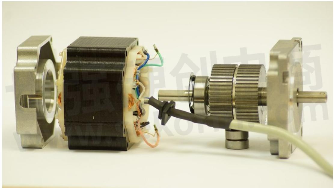
How Stepper Motors Work
Arduino step motors work similarly to servos, but with some key differences that make it easier to gain precise control over the motor’s movements. In a step motor, four coils form a ring around a rotor. Each coil is activated in succession, magnetically drawing the rotor towards it, rotating it 90 degrees. While this makes stepper motors slower than servos, they’re also much more precise, allowing for extremely controlled movement with minimal vibration. There are many types of Arduino step motors, but for this project, we’ll be using the common 28BYJ-48.
To control this step motor, you’ll also need a microcontroller that will handle all the complex movements. The step motor uses a high current, which means an IC like the ULN2003 is needed to control it. This driver board allows the low current Arduino to control the high current step motor. While you can find the IC on its own and wire it up manually, it’s a lot easier to find a driver board with the IC integrated directly into it.
We’ll also be using the built-in Stepper.h library which will make sending instructions to the step motor much simpler. This library will let you set the speed or number of steps that your motor will take with just a single line of code. This library is built into the Arduino IDE, so you won’t need to do anything special to enable it, but you can check out the documentation at the link above to see how it will work.
It’s also important to point out that since the step motor draws a high current, it’s best to use a separate power source for your final projects, rather than powering it off the Arduino. For the simple demonstration sketch in this guide, we’ll be using the 5V pin on the Arduino, but it can cause performance problems or even damage your board if you expand this project without carefully managing your power consumption. To keep everything working properly, make sure to power your step motor separately.
What You’ll Need
If you choose to get the ULN2003 driver board (which we highly recommend for this project), then the components for this project get a lot simpler. If not, you’ll need more wiring for your breadboard. In general, here’s what you’ll need:
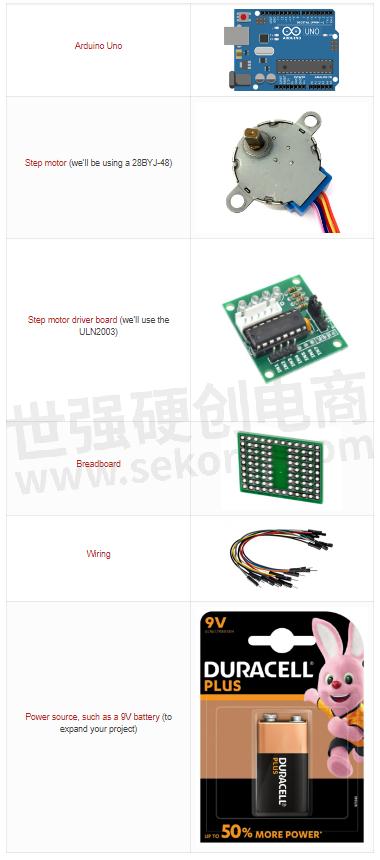
As explained above, the extra power source is to stabilize your step motor if you decide to expand this project. The demonstration sketch below should work safely with your Arduino Uno, but if you add more components that can draw extra power from your Arduino, be sure to swap out the Arduino power for an external power source.
The Code
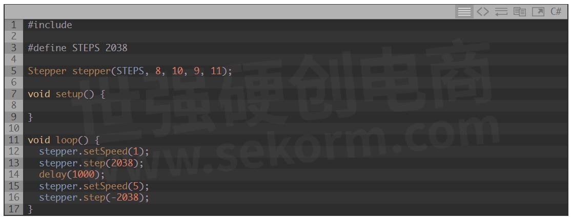
For this project, we’re simply going to rotate the step motor in one direction, and then the other. Take the code below and upload it to your Arduino.
Now, let’s break down the code step by step (so to speak!).
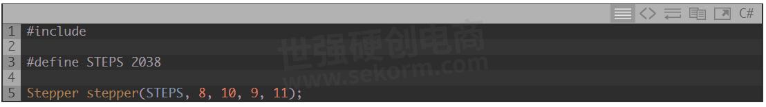
The first line here will tell the sketch to include the Stepper.h library, which you’ll need for controlling the step motor. Next, you’ll define the steps variable, determining how many steps are required for a full revolution. In this step motor’s case, this number is 2038, but check the datasheet for your motor, if you’re using a different component.
Finally, we’ll define a stepper object and assign it to pins 8, 10, 9, and 11, which will control the coils inside the step motor independently.
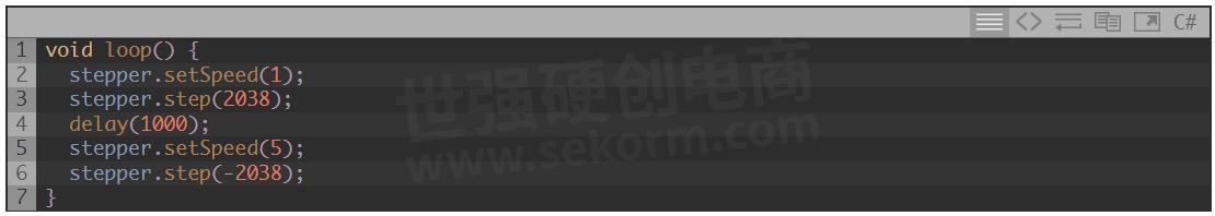
Inside the main loop, we’ll use two commands to set the speed the motor should turn at, and how far it should go. In this case, we’ll spin it for 2038 (or a full revolution) at 1 rotation per minute (or rpm). This will show you the baseline speed at which the step motor will turn.
Next, the code will delay for one second before turning back in the opposite direction (as indicated by using a negative value on the number of steps to take), but we’ll change the speed to 5rpm. Now, you’ll see the step motor move more quickly. This can help you get a frame of reference for how to control the motion of your step motor.
The Wiring
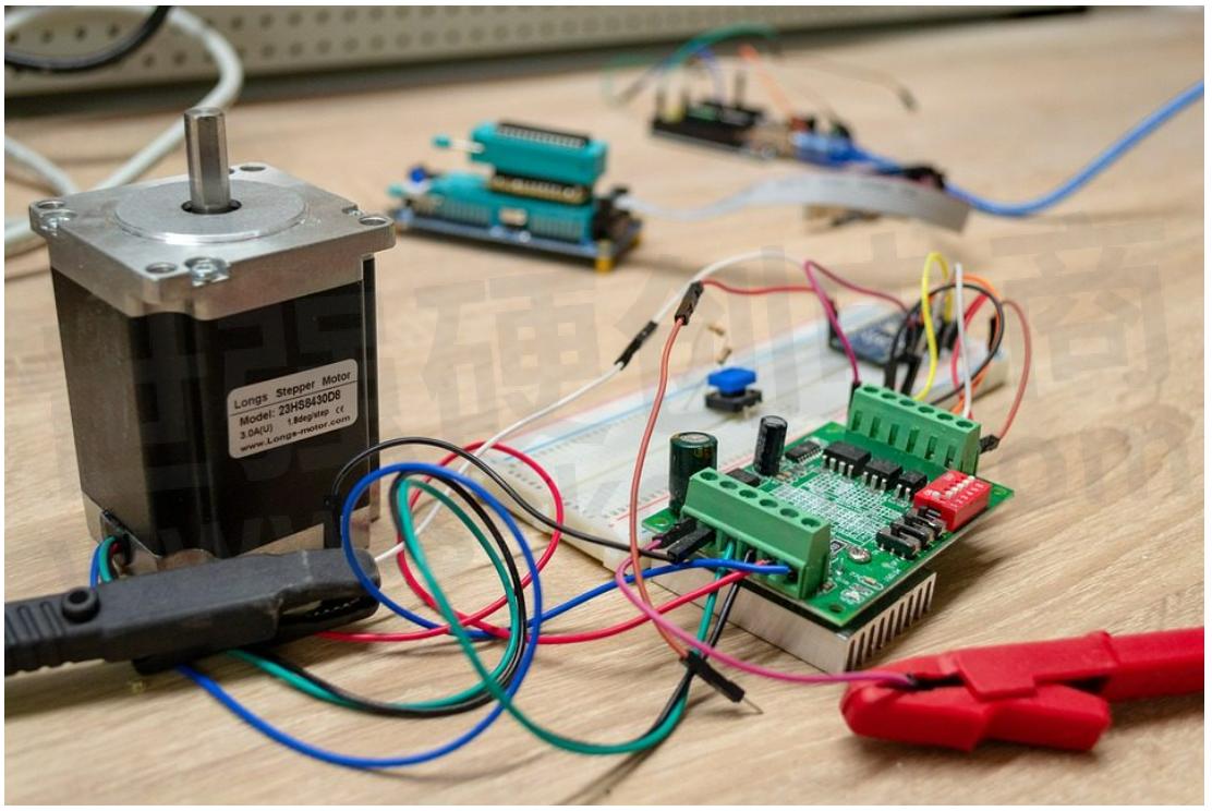
If you’re using the recommended driver board, then wiring for this project is very simple. You’ll only need six wires. However, keep in mind that this project will be drawing power from Arduino. If you expand this project at all, substitute a separate power source (such as a 9V battery, but check the requirements of your step motor for precise power requirements) in the places below where power and ground are connected to the Arduino.
To follow our demo sketch, connect these wires:
Connect the power pin on the driver board to 5V on the Arduino.
Connect the ground pin on the driver board to GND on the Arduino.
Connect pin IN1 on the driver board to pin 8 on the Arduino.
Connect pin IN2 on the driver board to pin 9 on the Arduino.
Connect pin IN3 on the driver board to pin 10 on the Arduino.
Connect pin IN4 on the driver board to pin 11 on the Arduino.
Once these parts are connected, you should be able to control the motor with just a few lines of code in your Arduino. Once you’ve connected a separate power source to your driver board, try experimenting with the code to turn based on input from a sensor or changing the speed or direction at which they turn.
- +1 Like
- Add to Favorites
Recommend
- Stepper Motor Drivers with Built-in Micro-stepping Algorithm Solveing the Jitter and Noise Problems
- UNIMOTION‘s Stepper Systems Offering a Complete Solution of a Stepper Motor, Drive and Cables
- The New RA6T1 Motor Control Rssk:Only Three Simple Steps to Use
- NOVOSENSE Introduces New Automotive-Grade Programmable Stepper Motor Driver NSD8381-Q1
- RX72M offers effortless evaluation of stepper motor control with EtherCAT
- Run a motor with encoder interface by using MCU RA6T1 motor control RSSK
- Dual-channel H-bridge Motor Driver Chip AT8841,2 Bits Current Control, Providing 4 Current Steps
- Master Micromachining: SANYO DENKI Stepper Motor System’s Superior Accuracy and Speed
This document is provided by Sekorm Platform for VIP exclusive service. The copyright is owned by Sekorm. Without authorization, any medias, websites or individual are not allowed to reprint. When authorizing the reprint, the link of www.sekorm.com must be indicated.
Integrated Circuits


Discrete Components


Connectors & Structural Components


Assembly UnitModules & Accessories


Power Supplies & Power Modules


Electronic Materials


Instrumentation & Test Kit


Electrical Tools & Materials


Mechatronics


Processing & Customization


