The RF Characteristics That Define the Performance of a Filter

Today, UIY’d like to discuss further the RF characteristics of the Filter and how it defines its performance.
Usually, the RF characteristics used to describe the filter performance are:
Orders (Stages)
Absolute bandwidth / Relative bandwidth
Cutting frequency
VSWR
Out-of-band rejection
Ripple in band
Insertion loss
Flatness in band
Phase linearity
Absolute group delay
Group delay variation
Power capacity
Phase consistency
Amplitude consistency
Operating temperature
These RF performance indicators of the filter are explained one by one as follows.
Orders (Stages): For high-pass and low-pass filters, the steps are the sum of the number of capacitors and inductors in the filter. For a bandpass filter, the steps are the total number of parallel resonators; for a band stop filter, the order is the total number of series resonators and parallel resonators.
Absolute bandwidth/relative bandwidth: This indicator is usually used for bandpass filters, which characterize the signal frequency range that can pass through the filter and reflects the frequency selection of the filter. Relative bandwidth is the percentage of absolute bandwidth to the center frequency.
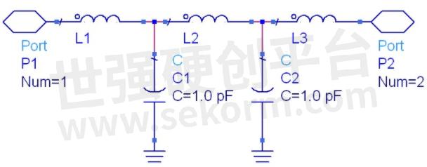
Five orders Low Pass Filter
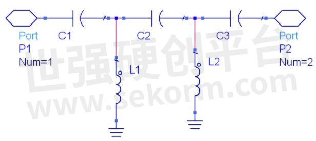
Five orders High Pass Filter
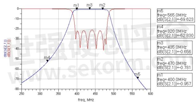
Six orders Band Pass Filter Stimulation Curve
Cutoff frequency: The cutoff frequency is usually used for high-pass and low-pass filters. For a low-pass filter, the cutoff characterizes the highest frequency range that the filter can pass. For a high-pass filter, the cutoff frequency characterizes the lowest frequency range that the filter can pass.
VSWR: It is the S11 measured by a vector network analyzer, which indicates the matching degree of the filter port impedance and the impedance required by the system. Indicates how much of the input signal fails to enter the filter and is reflected back to the input.
Nine orders Low Pass Filter Stimulation Curve
Insertion loss: It represents the energy lost after the signal passes through the filter, that is, the energy consumed by the filter.
Passband flatness: The absolute value of the difference between the maximum loss value and the minimum loss value within the passband range of the filter.
Out-of-band rejection: The amount of “attenuation” outside the frequency range of the filter’s passband. It shows the selectivity performance of a filter to unwanted frequency signals.
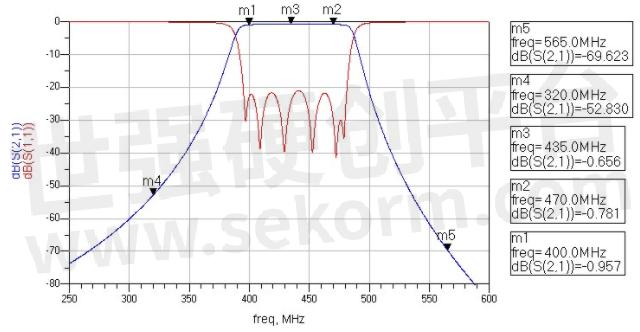
Band Pass Filter Stimulator curve
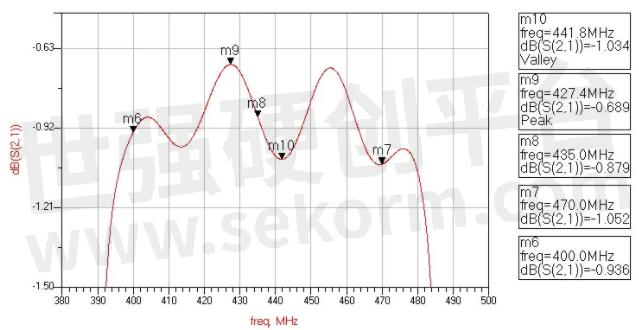
Ripple: The difference between the peak and trough of the undulating S21 curve within the passband of the filter.
Phase linearity: The phase difference between the phase in the passband frequency range of the filter and a transmission line with a delay equal to the center frequency. It characterizes the dispersion characteristics of the filter.
Absolute group delay: The time it takes for a signal within the passband of the filter to travel from the input port to the output port.
Group delay fluctuation: The difference between the maximum and minimum values of the absolute group delay within the passband of the filter. It stands for the dispersion characteristics of the filter.
Band Pass Filter Stimulator Curve

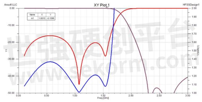
Band Pass Filter Stimulator Group Delay Curve
Power capacity: The maximum power of the passband signal that can be input to the filter.
Phase consistency: The difference in the phase of the transmission signal between different filters of the same index and the same batch. It characterizes the difference (consistency) between batches of filters.
Amplitude consistency: The difference in transmission signal loss between different filters of the same index and the same batch. It characterizes the difference (consistency) between batches of filters.
Operating temperature: The temperature range in which the filter can work normally according to the required parameters. It is used to characterize the adaptability of the filter to the temperature environment.
Filters of various structures have their own performance characteristics, and these characteristics correspond to different application occasions.
It does matter on selecting the right filter to improve the system performance of multiple requirements.
- +1 Like
- Add to Favorites
Recommend
- Filter Basics about Different Approaches to Q Factor
- Switch Filter Banks for Agile RF Receiver Design in Radar
- How to Use the Different Frequency Dependencies to Manipulate Impedance and Create Various Filter Responses?
- Knowles Precision Devices Introduces the SFSW Series of Hermetic, Panel-Mount EMI Filters
- Knowles Microstrip Filter Helps Your Thin Film RF Devices to Achieve the Best Performance
- Planar Filter Technology for Millimeter Wave Applications
- Expanding Knowles‘ Filter Technology Offerings to Serve Low-Frequency Applications
- What is Filter Shape Factor and Selectivity?
This document is provided by Sekorm Platform for VIP exclusive service. The copyright is owned by Sekorm. Without authorization, any medias, websites or individual are not allowed to reprint. When authorizing the reprint, the link of www.sekorm.com must be indicated.
Integrated Circuits


Discrete Components


Connectors & Structural Components


Assembly UnitModules & Accessories


Power Supplies & Power Modules


Electronic Materials


Instrumentation & Test Kit


Electrical Tools & Materials


Mechatronics


Processing & Customization


