What is Filter Shape Factor and Selectivity?

An Ideal Filter
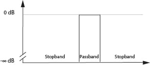
The Ideal Filter would have a unit gain (0dB) in its passband and a gain of zero (-infinity dB) in its stop band. Between the pass band and stop band, there would be no indecision and would transition from 0dB to -infinity dB asymptotically. It would pass only the required frequencies without adding or subtracting anything from the signal and like a very discrete and fastidious butler we would not see it - just its perfect management of the frequencies in its care.

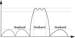
Sadly we cannot have perfect filters in the real world and so we compromise and accept some amount of non-unity gain in the pass band (insertion loss and passband ripple) and non-zero gain in the stop band (finite stop band attenuation and stopband ripple). In addition, there is some transition from pass band to stop band that needs to be understood and managed. This Transition Band can be a defining characteristic in the usefulness of a filter for a given application and is talked about using the terms Shape Factor and Selectivity.

Filter Shape Factor
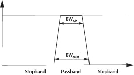
Usually, the shape factor is defined as shown in Figure 3 (which shows an otherwise ideal filter with just the addition of transition bands) and equation 1.


The transition band characteristics we are usually interested in a deal with the shape or steepness of the roll-off between the pass band and the stop band. Usually, the shape factor is defined as shown in Figure 3 (which shows an otherwise ideal filter with just the addition of transition bands) and equation 1. It is defined for two levels of attenuation and is usually taken to be the ration between 3dB of attenuation (passband) and a given stopband attenuation. For example, we could take 3dB to define the pass band and 60dB to use the stop band, and then use equation 1 to calculate the shape factor. Our ideal filter would have a shape factor of unity, but where this is not physically realizable we seek the smallest shape factor we can. For reference, simple RLC filters might have shape factors in the range of ~3, and SAW filters in the range of ~1.5.
Selectivity
The shape factor is a common figure of merit for a related term, selectivity. For an RF filter selectivity tells us how much of the total bandwidth will be used by transition bands. The smaller the transition bands the smaller any necessary guard bands can be and less of the bandwidth is wasted in this way. Selectivity is also discussed in terms of the steepness of the filter skirts and is often characterized in terms of so many dB of attenuation from the pass band at a given offset. In this, we can begin to see how filters selectivity can be a critical specification when it comes to its suitability for a given application since often a systems transmission and reception characteristics are given in terms of not just insertion loss in the pass band but clearly prescribed attenuation requirements in the stop band.
The selectivity of a filter is closely related to both the Q factor of the filter and the complexity of a filter (in terms of order).
Q Factor and Selectivity
The q factor of a filter can be defined as

As we reduce the bandwidth of our filter Q increases, the skirts become steeper and our filter becomes more selective. A bandpass filter increases in selectivity as Q increases.
Filter Order and Selectivity
The number of resonators (n) used in a filter design defines the filter order.

In general, we can design for steeper skirts (a “sharper filter”) with higher order filter designs, but at the cost of increased insertion loss and filter size.
Using filter technology that is inherently high Q, to begin with, is beneficial for high selectivity designs since the Q (and the low insertion loss that comes with this) can be balanced against the necessary order of the design that would otherwise be required to hit a given selectivity target. This is why acoustic wave filters (e.g. SAW and BAW) have been so popular at frequencies below 2GHz – at those frequencies, the physics of containing an acoustic wave inside a small package leads to very high Q factors and as a consequence excellent selectivity at the frequencies where SAW and BAW perform well.
Selectivity of Receivers
Applied to systems, selectivity is a receiver’s ability to discriminate between signals having different frequencies. Selectivity is often expressed as a ration in dB that compares the signal strength received with that of a similar signal at a different frequency. Depending on the location of the other (unwanted) signal relative to the desired signal, and the type of standard being discussed, selectivity can be discussed as adjacent channel rejection (ACR), adjacent channel selectivity (ACS), in-band blocking, and out-of-band blocking.
The need for selectivity in a receiver and the ability of available filters to deliver can strongly influence receiver architecture. Selectivity can be obtained with suitable filters at the RF stage of a receiver, but if the bandwidth and stopband attenuation requirements cannot be met with an RF filter another option is to down-convert the signal and implement high selectivity at the IF stage such as in a superheterodyne receiver. This approach however necessitates image rejection filters – so the ability to achieve reasonable levels of selectivity at RF can simplify architecture choices. In fact, sufficiently high selectivity close to the antenna can significantly simplify the demodulation electronics downstream.
In this short introduction to Shape Factor and Selectivity, we have seen how real-world filter deviation from ideal behavior needs to be quantified and that in the transition band, common tools to do that are shape factor and selectivity. We have touched on how both resonator Q and the filter order (number of resonators in a design) can influence the behavior of a filter in the transition band. And we have seen how the topic of selectivity can expand out to influence the behavior and complexity of a receiver and how well it can perform relative to system-level specifications such as ACR and ACS.
- +1 Like
- Add to Favorites
Recommend
- Knowles Precision Devices Introduces the SFSW Series of Hermetic, Panel-Mount EMI Filters
- Knowles‘ Microstrip Filters Offer a High Repeatability and Temperature Stability from -55℃ to 125℃
- Filter Basics about Different Approaches to Q Factor
- Switch Filter Banks for Agile RF Receiver Design in Radar
- How to Use the Different Frequency Dependencies to Manipulate Impedance and Create Various Filter Responses?
- Knowles Microstrip Filter Helps Your Thin Film RF Devices to Achieve the Best Performance
- The Role of EMI Filters in Power Electronics
- Planar Filter Technology for Millimeter Wave Applications
This document is provided by Sekorm Platform for VIP exclusive service. The copyright is owned by Sekorm. Without authorization, any medias, websites or individual are not allowed to reprint. When authorizing the reprint, the link of www.sekorm.com must be indicated.


