Planar Filter Technology for Millimeter Wave Applications

The advent of fifth generation (5G) communications brings an increased interest in Millimeter Wave (mmWave) technologies. One of the biggest technology challenges engineers face with 5G is how to implement sufficiently high-performance RF filtering in mmWave applications. Given the frequencies involved a distributed element planar approach, such as using Microstrip or Stripline, is often ideal for constructing resonators and filters.In this paper Knowles will share Planar Filter Technology for Millimeter Wave Applications.
Planar Filter Overview
Planar filters are manufactured by creating flat 2D resonators with patterns of strip elements on a dielectric substrate. Depending on the filter topology, Planar filters can offer a high quality factor (Q) and a reasonable approach to achieving performance in a small footprint. The structure of Planar filters is similar to a printed circuit board, but with the key distinction that the metal conductor patterns printed on the solid dielectric substrate are there to create resonators rather than just interconnects.
The width of a strip element, the dielectric constant of the substrate and its thickness determine the characteristic impedance. Changing the characteristic impedance by changing the structure of the strip element creates a discontinuity in transmission characteristics, and it is this effect that is used to create distributed element systems that mimic the properties of a lumped element circuit.
Discontinuities in the transmission line are engineered to present a reactive impedance to the wave propagating through the line. These reactances can be designed to serve as approximations for lumped inductors, capacitors, or resonators, depending on what is needed for the filter. Thus, a wide range of distributed element filter topologies have been developed, including the following four types:
End-Coupled – Consists of sections of transmission line a half wavelength long at the center frequency of the bandpass filter that act as resonators and are coupled across capacitive gaps in the transmission line.

Parallel-Coupled – Constructed so that adjacent resonators are parallel to each other along half of their length. This arrangement gives relatively large coupling between resonators, and as a result, this topology has the advantage of wider bandwidth compared to the end coupled approach.

Interdigital filters – In this topology, each resonator is a quarter wavelength long and is terminated in a short circuit at one end with the other end being left open-circuit, with the orientation alternating.

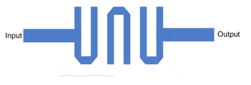
Hairpin – If you imagine folding the resonators in the parallel coupled filter, resulting in a ‘U’ shape, this is how a hairpin topology is configured.

While there are other major factors to consider when implementing a Planar filter, such as substrate choice, defining topology options for your application is a great first step to addressing the challenges presented by filtering mmWaves for 5G applications.
- +1 Like
- Add to Favorites
Recommend
- 5 Key Reasons to Choose a Planar Filter Over Conventional Filter Technology in Your Next RF Design
- Smiths Interconnect Announced Planar X Series of RF Filters with Highpass Configurations up to 18GHz (Ku Band)
- Planar Filters Continue to Advance
- Smiths Interconnect New Lowpass RF Filter Solutions in the X Band Ideal for Radar, SATCOM, and Satellite Industries
- ATP Offers 3D NAND Flash in Various Form Factors With Capacities Ranging From 128 Gb to 1 Tb, Better Than Planar Nand Solutions
- Planar SMD Zener Diode ZMM3.3 Help to Run the Battery Powered Toy Even Longer
- Maplesemi‘s 60V/80A N-Channel MOSFET SLD80N06T Using Advanced Planar Stripe TRENCH Technology
- Knowles to Participate in Upcoming Baird Conference in New York on June 4, 2024
This document is provided by Sekorm Platform for VIP exclusive service. The copyright is owned by Sekorm. Without authorization, any medias, websites or individual are not allowed to reprint. When authorizing the reprint, the link of www.sekorm.com must be indicated.


