Xiangru Electronics Introduced an Integrated Inductor XR0630-4R7M, with a Maximum Dc Resistance of Only 42mω and a High Saturation Current of 7A

Abstract
Miniaturization of electronic products is a trend of sustainable development, which has brought remarkable advantages in many application fields, such as PAD, smart phones, portable game devices, smart wear, power modules and so on. With the continuous enhancement of electronic products' functions and thinner designs, the requirements for the size and performance of inductors are also increasing. To meet the market demand, Xiangru Electronics introduced the inductor XR0630-4R7M, which has the characteristics of high power, high saturation current, low impedance and miniaturization. With advanced integrated molding technology, miniaturization is realized, and at the same time, it has high reliability, which meets the requirements of miniaturization and high reliability of electronic products.
Product Features
Small size: the overall size is only 7.6 * 6.6 * 3.0 mm;
High saturation current (typical 4A, maximum 7a);
Adopt shielding design to reduce the difficulty of EMI design of products;
The surface adopts vinyl thermal spraying process, which has good surface compactness;
100% lead-free process, meeting RoHS2.0, halogen-free, REACH and other standards;
Low DC resistance: The maximum DC resistance is only 42mΩ, and it has the characteristics of low power consumption.
Appearance and Size
The following figure shows the structure and dimensions of XR0630-4R7M integrated inductor. Compared with the conventional inductor structure, this structural design has the following characteristics and advantages:
The overall size is only 7.6 * 6.6 * 3.0mm. This integrated inductor is very small in size and occupies very little PCB space, which is helpful to save circuit board space and is especially suitable for smart wear, power module and other products.
Magnetic shielding structure: As we all know, inductance has a rapid di/dt change in circuit applications, which makes it a typical radiation source. In the process of product design, if the inductor with non-magnetic shielding structure is used, the EMC design principle must be considered in advance for its circuit design. Otherwise, it will cost a lot of time and money to rectify the product after the product fails the EMC test or the system works abnormally due to EMC problems. The integrated inductor has a magnetic shielding structure, the magnetic circuit is closed, and the leakage radiation of magnetic lines is very small, which can effectively reduce the external electromagnetic radiation and solve the EMC problem of products.
Small squeal of the inductor: The integrated molding technology makes the coil and magnetic powder closely combined, which reduces the vibration amplitude of the inductor coil structurally, thus reducing the squeal of the inductor. This can reduce the external noise of the whole product, especially suitable for smart wearable products with high mute requirements.

Specification Parameter
The nominal value of inductance is 4.7μH, and the error value is 20%. The design can refer to typical application circuits.
The maximum DC resistance is only 42mΩ, which will greatly reduce the loss of the inductor itself, improve the conversion efficiency and reduce the calorific value. It is very suitable for products with low energy consumption and low fever, such as PAD, smart phone, portable game equipment, WI-FI module notebook, etc.
The rated current is 4.0A, and the maximum peak current is 7A. It is suggested that the derating factor should be 0.7 in the circuit design, which can keep the inductor high reliability and prolong its service life. The characteristic of high saturation current also enables the inductor to work for a long time in a large current environment.

Specification Parameter
Typical Application Scheme
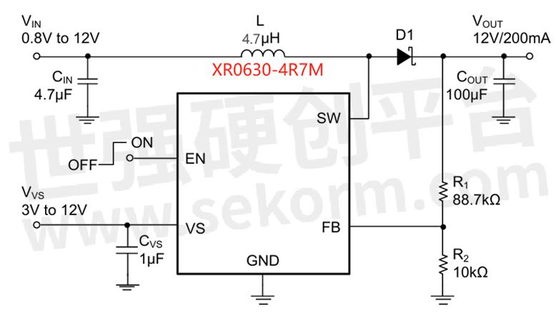
As shown below, it is a typical application scheme of miniaturized integrated XR0630-4R7M inductor in switching power supply boost circuit. The input voltage range of this application scheme is 0.8V~12V, the output voltage is 12V, and the maximum load current is 200mA.
The working principle and inductance function of the circuit are briefly explained as follows: the inside of the SW pin is a MOS tube control circuit. When the MOS tube is turned on, the input voltage charges the inductor, and the voltage Zuo Zheng at both ends of the inductor is negative; When the MOS transistor is turned off, the inductor voltage is reversed, left negative and right positive, and superimposed on the input voltage to charge the capacitor Cout to 12 V.. Inductor plays an energy storage role in it, and its miniaturization, low impedance and high saturation current characteristics can reduce the size of power module and maintain high conversion efficiency.

Typical Application Circuit
Applied Range
DC/DC power supply;
PAD, smart phone, portable game device, smart wear; WI-FI module notebook, VR, AR;
CD display, HDDS, DVCS, DSCS;
Baseband power supply, amplifier, power supply module, camera power supply and so on.
Production Situation
Mass production
- +1 Like
- Add to Favorites
Recommend
- Integrally Formed Inductor Recommended for TWS Earphones: XRTC252012S2R2MBCA from Xiangru Electronics Has a Low DC Resistance of Only 65mΩ
- The Xiangru Electronics XRT953B-351M Common Mode Toroidal Inductor Provides Excellent EMC Performance for Charging Station Products
- Xiangru Electronics XRSQ1010-10mH-H High Performance SQ Flexible Flat Cable Common Mode Choke, Helping the Miniaturization Design of Power Products
- Xiangru Electronics Introduced the Unshielded Inductor XRCD32-220K, with a Size of Only 3.5*3.0*2.1mm, Which Helps the Small and Lightweight Design of Products
- XRTC252012S2R2MBCA Integrated Inductor Introduced by Xiangru Electronics Has a DC Resistance as Low as 55mΩ, Realizing Low Loss
- Design of Ultrasonic Drive Circuit for Xiangru Electronic Patch Transformer with Limited Assistance Space is Only 9*7*6.7mm in Size
- Comprehensive Guide to Capacitor Detection and Selection
- The Inductor Coil Manufacturer Briefly Describes the Performance Indicators of the Inductor Coil for You
This document is provided by Sekorm Platform for VIP exclusive service. The copyright is owned by Sekorm. Without authorization, any medias, websites or individual are not allowed to reprint. When authorizing the reprint, the link of www.sekorm.com must be indicated.


