Design of Ultrasonic Drive Circuit for Xiangru Electronic Patch Transformer with Limited Assistance Space is Only 9*7*6.7mm in Size

Ultrasonic ranging technology is a technology that uses ultrasonic signals to measure the distance. It calculates the actual distance from the launch point to the obstacle by measuring the time when the ultrasonic waves meet the obstacle after launch and according to the propagation speed of sound waves. This technology has the characteristics of high precision, non-contact measurement and strong directionality, and is widely used in industrial production, medical diagnosis, security monitoring, smart home and automobile fields.
ultrasonic ranging principle
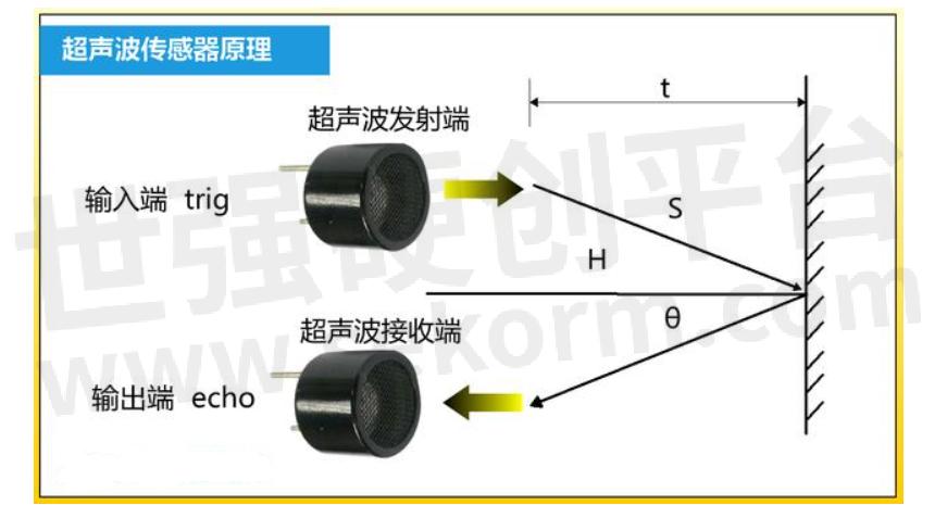
As shown in Figure 1, the principle of ultrasonic ranging is that the propagation speed of ultrasonic wave in the air is known, and the time when the sound wave meets an obstacle after transmission is measured, and the actual distance from the transmission point to the obstacle is calculated according to the time difference between transmission and reception. The propagation speed of ultrasonic wave in the air is 340m/s, and the distance L from the emission point to the obstacle can be calculated according to the time t seconds recorded by the timer, that is, L= C×T/2.

Fig. 1
Ultrasonic drive circuit
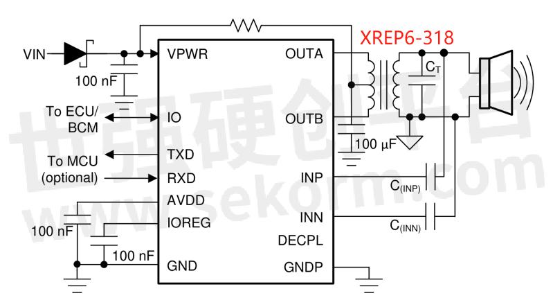
Ultrasonic driving circuit usually consists of excitation source (pulse generator), driving amplifier, impedance matching network, step-up transformer, ultrasonic transducer and signal processing circuit, as shown in Figure 2. Among them, the step-up transformer plays a vital role. It is mainly used to convert low power supply voltage into high voltage to meet the high voltage driving conditions required by ultrasonic transducers. This conversion is necessary because the ultrasonic transducer needs to work at high voltage to generate enough acoustic energy.

Fig. 2 Typical circuit diagram of ultrasonic drive
The function of step-up transformer can be summarized as follows:
1. Voltage conversion: converting a low voltage into a high voltage to drive an ultrasonic transducer.
2. Isolation: provide electrical isolation to protect other parts of the circuit from high voltage.
3. Impedance matching: Match the load impedance of the ultrasonic transducer with the output impedance of the power supply to maximize the energy transfer efficiency.
4. Frequency response: In some designs, the step-up transformer can be designed to work at a specific frequency to optimize the performance of the ultrasonic transducer.
Although the performance of the ultrasonic driving circuit is greatly improved by using the driving circuit of the transformer, due to the existence of the transformer and the volume of the driving circuit, in some products with limited design space, such as unmanned aerial vehicles and vehicle-mounted radars, LC resonance boosting scheme can only be abandoned. Therefore, the XREP6-318A patch transformer of XIANGRU ELECTRONICS is recommended, and its volume size is only 9mm*7mm*6.7mm, as shown in Figure 3, which can solve the problem of limited product volume design space.

Fig. 3 Structural diagram of XREP 6-318a SMD transformer
Specification parameters and application advantages
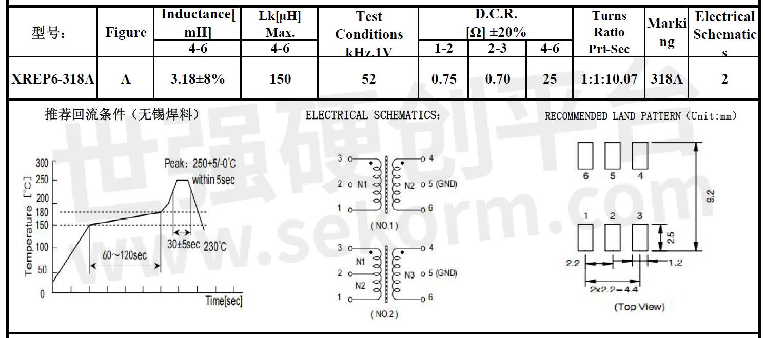
Xiangru electronic XREP6-318A SMD transformer secondary winding 4-6 has a low leakage inductance of only 150μH h.. Its low leakage inductance can bring significant benefits to the performance of ultrasonic driving circuit. First of all, under the condition of high frequency driving, low leakage inductance can reduce the generation of peak voltage, thus maintaining the stability of voltage waveform. Secondly, low leakage inductance can reduce energy loss and improve the efficiency of the whole energy conversion circuit, especially in high frequency applications. Finally, low leakage inductance helps to reduce EMI (electromagnetic interference) and improve the pass rate of products such as ultrasonic radar in related EMC tests, such as terminal voltage, radiation emission and conducted emission.
The parameters of XREP6-318A SMD transformer are measured at the general working frequency of 52kHz, while the ultrasonic working frequency ranges from 20kHz~ to GHz, so it can meet the design requirements of ultrasonic driving circuit. Combined with the transducer design, the working frequency of the transformer can work at the resonant frequency of the transducer to achieve the maximum energy conversion efficiency. However, it should be noted that the power capacity of the transducer should be considered in the specific design and application to ensure that the circuit will not exceed the bearing capacity of the transducer.

Fig. 4 specification parameters of xrep6-318a SMD transformer
To sum up, Xiangru Electronics' XREP6-318A patch transformer is compact in size of 9mm*7mm*6.7mm and low in leakage inductance of 150μH, which can not only solve the problem of tight space for product designers and reduce the difficulty of EMC design, but also meet the design requirements of ultrasonic drive circuit and achieve maximum energy conversion efficiency.
- +1 Like
- Add to Favorites
Recommend
This document is provided by Sekorm Platform for VIP exclusive service. The copyright is owned by Sekorm. Without authorization, any medias, websites or individual are not allowed to reprint. When authorizing the reprint, the link of www.sekorm.com must be indicated.


