What is Board To Board Connectors?

1. What is the size, current and voltage rating of this connector?
Board To Board Connectors are widely used in electronic devices to establish a connection between two circuit boards. These connectors come in various sizes, current ratings, and voltage ratings to accommodate different application requirements.
The size of Board To Board Connectors can vary depending on the specific model and manufacturer. They are available in different pitch sizes, which refer to the distance between the center of one pin to the center of the adjacent pin. Common pitch sizes for board to board connectors include 0.8mm, 1.27mm, 2.0mm, and 2.54mm. The choice of pitch size depends on factors such as space constraints and signal density.
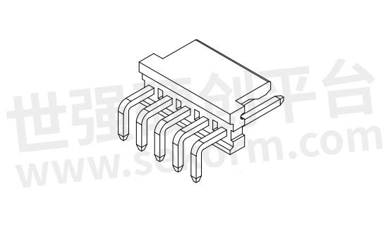
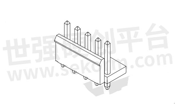
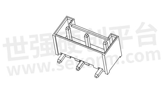
The current rating of board to board connectors represents the maximum current that the connector can safely carry without overheating or causing damage. The current rating is specified by the manufacturer and can vary depending on the connector design and construction. Board to board connectors typically have current ratings ranging from a few milliamperes (mA) to several amperes (A), depending on the size and configuration of the connector.
The voltage rating of board to board connectors signifies the maximum voltage that the connector can safely handle without experiencing electrical breakdown or arcing. The voltage rating is also specified by the manufacturer and can differ based on the connector's insulation materials and design. Board to board connectors typically have voltage ratings ranging from a few volts (V) to several hundred volts (V), depending on the specific model and application.
It is important to select a board to board connector with the appropriate size, current rating, and voltage rating for the specific application. Using a connector with insufficient current or voltage ratings can lead to unreliable connections, electrical failures, or even damage to the circuit boards.
When choosing a board to board connector, it is also crucial to consider other factors such as the number of contacts/pins, the mating/unmating forces, and the mating/unmating cycles. These factors ensure a secure and reliable connection between the boards, as well as the durability of the connector over its lifetime.
In conclusion, board to board connectors come in various sizes, current ratings, and voltage ratings to cater to different electronic applications. Selecting the right connector with the appropriate specifications ensures a reliable and safe connection between circuit boards, contributing to the overall performance and longevity of electronic devices.
2. Are there different socket types to choose from?
Yes, there are different socket types available for board-to-board connectors. The choice of socket type depends on the specific requirements of the application.
One type of socket commonly used in board-to-board connectors is the through-hole socket. Through-hole sockets have leads that pass through holes in the circuit board and are soldered on the other side. These sockets provide secure and stable connections and are suitable for applications that require high reliability.
Another type of socket is the surface mount socket. Surface mount sockets do not have leads that go through the board, but instead have flat contacts that are soldered directly onto the surface of the board. Surface mount sockets are smaller in size and allow for more compact designs. They are commonly used in applications where space is limited.
In addition to through-hole and surface mount sockets, there are also press-fit sockets available. Press-fit sockets have pins that are pressed into plated through-holes on the board, creating a reliable electrical connection. Press-fit sockets are often used in applications where frequent board replacement or repair is required, as they can be easily removed and replaced without the need for soldering.
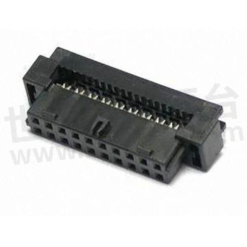
Furthermore, there are also board-to-board connectors with mixed socket types. These connectors offer a combination of through-hole, surface mount, or press-fit sockets in a single connector, allowing for flexibility in design and installation.
It is important to select the appropriate socket type based on factors such as the board type, application requirements, and available manufacturing processes. The choice of socket type will impact the ease of installation, reliability of the connection, and overall performance of the board-to-board connector.
In conclusion, there are different socket types available for board-to-board connectors, including through-hole, surface mount, press-fit, and mixed socket types. Each socket type has its own advantages and is suitable for specific applications. Careful consideration of the application requirements is necessary to select the most appropriate socket type for a board-to-board connector.
3.Main purposes and application areas
Board To Board Connectors, also known as inter-board connectors, are essential components used in electronic devices to establish connections between two or more circuit boards. These connectors play a crucial role in enabling the transmission of signals, power, and data between different PCBs within a system. Board To Board Connectors come in a variety of types, sizes, and configurations to accommodate the specific requirements of different applications.
The main purposes of Board To Board Connectors include:
Signal Transmission: Board To Board Connectors facilitate the transfer of electrical signals between circuit boards, ensuring a reliable and efficient communication pathway within electronic devices. These connectors help maintain signal integrity and minimize signal loss during transmission.
Power Distribution: Board To Board Connectors are used to distribute power between different PCBs within a system. They provide a secure and stable connection to ensure the smooth flow of power throughout the electronic device.
Data Transfer: Board To Board Connectors enable the exchange of data between interconnected circuit boards. They support high-speed data transfer rates and help maintain a consistent data connection for seamless communication within the system.
Modular Design: Board To Board Connectors feature a modular design that allows for flexibility and scalability in electronic device design. They enable the easy assembly and disassembly of circuit boards, making them ideal for applications that require frequent board changes or upgrades.
Board To Board Connectors find a wide range of applications across various industries, including:
Telecommunications: Board To Board Connectors are used in telecommunications equipment such as routers, switches, and modems to establish connections between different PCBs for signal processing and data transmission.
Computer Systems: Board To Board Connectors play a vital role in computer systems, connecting components such as memory modules, expansion cards, and interface boards to the motherboard for seamless operation.
Automotive Electronics: Board To Board Connectors are utilized in automotive electronics for applications such as in-vehicle infotainment systems, engine control units, and sensor modules to facilitate communication between different electronic components.
Industrial Automation: Board To Board Connectors are essential in industrial automation equipment for connecting control panels, motor drives, and sensors to enable efficient and reliable automation processes.
Medical Devices: Board To Board Connectors are used in medical devices such as patient monitoring systems, diagnostic equipment, and imaging devices to establish connections between PCBs for data processing and communication.
In conclusion, Board To Board Connectors are versatile components that play a critical role in enabling connectivity and communication between circuit boards in electronic devices. Their wide range of applications and importance in various industries highlight their significance in modern electronic systems.
4. How durable and reliable is it?
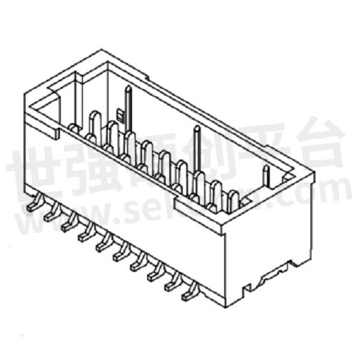
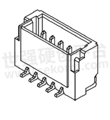
Board-to-board connectors are designed to provide a durable and reliable connection between two circuit boards. The durability and reliability of these connectors depend on various factors, including the quality of the materials used, the design of the connector, and the manufacturing processes employed.
To ensure durability, board-to-board connectors are often constructed using high-quality materials that offer excellent mechanical strength and resistance to external forces, such as vibrations and shocks. Common materials used for connector bodies include thermoplastic resins, which provide good resistance to wear and tear, as well as metal alloys like brass or phosphor bronze, which offer high conductivity and corrosion resistance.
The reliability of board-to-board connectors is crucial in maintaining the integrity of the electrical connection. Connectors with well-designed contact systems ensure consistent and reliable electrical connections between the boards. These contact systems may include features such as multiple points of contact, gold-plated contacts for improved conductivity and corrosion resistance, and self-cleaning mechanisms that remove any debris or contaminants that may affect the connection.
Moreover, board-to-board connectors undergo rigorous testing during the manufacturing process to ensure their reliability. These tests may include checks for mechanical strength, electrical performance, and resistance to environmental factors such as temperature and humidity. Manufacturers often adhere to industry standards and certifications to guarantee the quality and reliability of their connectors.

In addition to the materials and design, the reliability of board-to-board connectors also depends on proper installation and mating. It is important to follow the manufacturer's guidelines and specifications for installation, including correct alignment and mating forces. Improper installation can lead to loose connections, which may result in electrical failures or intermittent signals.
Overall, board-to-board connectors are designed to provide a durable and reliable connection between circuit boards. By choosing connectors from reputable manufacturers that adhere to industry standards, ensuring proper installation, and considering the specific requirements of the application, you can maximize the durability and reliability of your board-to-board connections.
In conclusion, board-to-board connectors are built to withstand external stresses and provide reliable electrical connections. The use of high-quality materials, well-designed contact systems, adherence to industry standards, and proper installation procedures contribute to the durability and reliability of these connectors. By selecting the right connectors and following best practices, you can ensure a robust and long-lasting connection between your circuit boards.
5. How does it work?
Board-to-board connectors are essential components that facilitate the connection between two separate circuit boards. These connectors are designed to provide a reliable and secure electrical interface, allowing for the exchange of signals and power between the boards.
The working principle of board-to-board connectors involves several key elements. Firstly, the connector consists of socket and header components. The socket is typically mounted on one circuit board, while the header is mounted on the other board. When the two boards are brought together, the socket and header align and mate, establishing electrical contact between them.
The connectors feature a contact system that enables the transmission of signals and power. The contact system consists of pins or contacts located within the socket and corresponding receptacles within the header. These pins and receptacles are designed to create a low-resistance and reliable connection.
Upon mating, the pins of the socket make contact with the receptacles of the header, creating an electrical pathway between the two boards. The pins and receptacles are engineered to ensure proper alignment and secure mating, preventing any accidental disconnections.
To enhance the electrical performance and reliability, some connectors incorporate additional features. Gold plating on the pins and receptacles improves conductivity and corrosion resistance, ensuring a stable connection over time. Some connectors also include shielding mechanisms to protect against electromagnetic interference (EMI) and reduce signal degradation.
Board-to-board connectors can support various types of signals, including digital, analog, and power signals. They are available in different configurations and pin counts to accommodate different board layouts and requirements. Some connectors also offer additional features such as locking mechanisms or latching systems to ensure a secure and vibration-resistant connection.
The working of board-to-board connectors is not only dependent on the connector itself but also on proper installation and mating. It is crucial to follow the manufacturer's guidelines for alignment, insertion force, and mating sequence to ensure a successful and reliable connection.
In conclusion, board-to-board connectors provide a vital link between separate circuit boards. Their working principle involves aligning and mating socket and header components to establish electrical contact. The contact system within the connector facilitates the transmission of signals and power between the boards. By selecting the appropriate connector and following proper installation procedures, a robust and reliable board-to-board connection can be achieved.
6. How to install and use?
Installing and using board-to-board connectors requires careful attention to ensure a proper and secure connection between the circuit boards. Below are the general steps to install and use board-to-board connectors:
Prepare the boards: Ensure that the two circuit boards are clean and free from any debris or contaminants that could interfere with the connection. Check that the boards are properly aligned and oriented for mating.
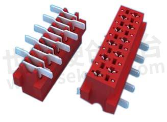
Select the appropriate connector: Choose a board-to-board connector that matches the specific requirements of your application, such as the number of pins, pin spacing, and voltage or current ratings. Consider factors like the available space, board thickness, and desired mating method (through-hole, surface mount, press-fit, etc.).
Mount the connector on the first board: If using a through-hole connector, insert the connector leads through the holes in the first board, ensuring they go through the correct corresponding pads. If using a surface mount connector, apply solder paste to the pads and carefully position and align the connector on the board. Then, reflow the solder to secure the connector in place.
Align the second board: Position the second board over the first board, aligning the connectors on both boards. Ensure that the pins or contacts on the second board align properly with the corresponding receptacles or sockets on the first board.
Apply mating force: Apply gentle and even pressure to mate the two boards together. Avoid using excessive force that could result in damage to the connectors or the boards. If the connectors have a specific latching or locking mechanism, engage it to ensure a secure connection.
Test the connection: Once the boards are mated, test the connection to ensure it is functioning correctly. Use appropriate testing equipment to verify the continuity of the electrical signals and the stability of the power supply. Troubleshoot any issues that may arise during testing.
Secure the connection: Depending on the application, consider adding additional measures to secure the connection, such as using screws, adhesives, or mounting brackets. These additional steps can provide extra stability and resistance to vibrations or shocks.
Follow manufacturer guidelines: Always refer to the manufacturer's guidelines and specifications for the specific board-to-board connectors you are using. The manufacturer's recommendations regarding installation, mating force, alignment, and any special considerations should be followed to ensure a reliable and durable connection.
It is important to note that the installation and usage process may vary depending on the specific type and design of the board-to-board connectors. Therefore, it is essential to consult the manufacturer's documentation and guidelines for precise instructions tailored to your chosen connectors.
In summary, properly installing and using board-to-board connectors involves preparing the boards, selecting the appropriate connector, mounting it correctly, aligning the boards, applying mating force, testing the connection, securing the connection if necessary, and following the manufacturer's guidelines. By carefully following these steps, you can establish a reliable and robust connection between circuit boards.
- +1 Like
- Add to Favorites
Recommend
- How to Check the Board to Board Connector of Mobile Phone?
- How to Mount Board to Board Connectors?
- ept One27® SMT PCB Connectors with a Pitch of 1.27mm is Suitable for Board-to-board Applications ∣ video
- How to Select the Right Board to Board Connector?
- How to Select Board-to-board Connectors?
- Function and Parameter Selection of Board-to-Board Connectors
- Features and Classifications of Board-to-Board Connectors
- Antenk Electronics Appeared in Guangzhou International Intelligent Manufacturing Exhibition with A Series of High-performance Connector Application Solutions
This document is provided by Sekorm Platform for VIP exclusive service. The copyright is owned by Sekorm. Without authorization, any medias, websites or individual are not allowed to reprint. When authorizing the reprint, the link of www.sekorm.com must be indicated.


