Design Concepts for EMI/EMP Filter Connector

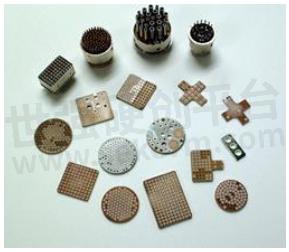
The heart of an EMI/RFI filter connector is the monolithic planar capacitor array. This is a barium-titanate ceramic disc, which provides a common substrate for capacitance on each line of a connector. The capacitance values can be mixed including ground and feed-thru lines. The typical range of capacitance available is 500 pF to 100,000 pF. The capacitor array also provides a continuous ground plane across the interface of the connector.

The capacitor arrays can be used in connectors to build C, L, Pi, and T filters. Ferrite beads are used to provide inductance of 0.5μH to 5μH, along with 10-100 ohms in the equivalent circuit. Because the capacitor is ceramic, it is relatively brittle in comparison to the other components of a connector (metal, rubber, and plastic). Therefore, the internal construction of the filter connector must isolate the capacitors from mechanical stress.
Smiths Interconnect uses a thin wall ground plane to house the filter elements. The ground plane is captured between halves of the connector shell to provide mechanical retention as well as electrical contact. Thermal stress from the connector shell is not transferred to the capacitor arrays due to a gap between the outside diameter of the ground plane and the inside of the shell. Stress from the contacts is eliminated through the use of a block of epoxy on either side of the capacitors.
Smiths Interconnect further isolates the capacitors with a proprietary expansion barrier between the epoxy and the capacitors. EMI/RFI and EMP protection can both be integrated into a connector with only a small increase in length over the non-filtered version. Smiths Interconnect's design approach for diode connectors is unique. Smiths Interconnect mounts the diodes around the outside of the contact arrangement on a multi-layer circuit board within the connector. The difference and feature of the design are described below:
• Standard military JANTX type diodes are used.
• The diodes are not special or sized down.
• The diodes are located outside the contact arrangement to allow for size and shape options. By doing so, the power/pulse width capability is preserved. This enables the diode manufacturer to produce the diodes in a familiar manner without special processes.
• The structure is modular in that the diodes are attached to multi-layer circuit board with the contact arrangement at its center permitting detachment. The circuit traces from the contact to the diode are kept as wide as possible and are sandwiched between ground planes. This provides a very low characteristic impedance strip line configuration, thus eliminating any "ringing" of pulse response.
• The diodes are removable, but not accessible to unauthorized personnel.
- +1 Like
- Add to Favorites
Recommend
- Filter Basics about Different Approaches to Q Factor
- Switch Filter Banks for Agile RF Receiver Design in Radar
- How to Use the Different Frequency Dependencies to Manipulate Impedance and Create Various Filter Responses?
- Filter Capacitor Comparison
- Knowles Precision Devices Introduces the SFSW Series of Hermetic, Panel-Mount EMI Filters
- Knowles Microstrip Filter Helps Your Thin Film RF Devices to Achieve the Best Performance
- Planar Filter Technology for Millimeter Wave Applications
- Expanding Knowles‘ Filter Technology Offerings to Serve Low-Frequency Applications
This document is provided by Sekorm Platform for VIP exclusive service. The copyright is owned by Sekorm. Without authorization, any medias, websites or individual are not allowed to reprint. When authorizing the reprint, the link of www.sekorm.com must be indicated.


