Filter Capacitor Comparison
The heart of the filter connector is the capacitor array. Smiths Interconnect uses monolithic ceramic capacitor array on both thick and thin film technology. Using a dry process to laminate the layers of X7R ceramic tape, Smiths Interconnect is capable of achieving capacitance values from 100pF to 100nF on the same array. Our extensive filtering capability allows for unique applications and arrangements not engineered elsewhere in the connector world. This may include mixed contact sizes, new insert arrangements, or high voltage applications up to 2000VDC Dielectric Withstand Voltages (DWV).
The planar array is much more complex and versatile in its design. The planar uses the same X7R material as the tubular capacitor, however the electrodes run perpendicular to the contact. This allows higher capacitance and higher voltage ratings, as the pin to pin spacing does not affect the design as much. With the electrodes running perpendicular to the contact, we can stack more electrodes thus increasing capacitance and at the same time, thicken the dielectric between electrodes to increase withstanding voltages.
The planar array also has the advantage of strength. As the layers of ceramics are stacked perpendicular to the contact, we can increase the planar thickness to about .100" to withstand high vibration scenarios as in the EFA. This far outweighs the .015" found in the Tubular capacitor. Because the capacitor is ceramic, it is relatively brittle in comparison to the other components of a connector (metal, rubber, and plastic). Therefore, the internal construction of the filter connector must isolate the capacitors from mechanical stress.
Smiths Interconnect uses a thin wall ground plane to house the filter elements. The ground plane is captured between halves of the connector shell to provide mechanical retention as well as electrical contact. Thermal stress from the connector shell is not transferred to the capacitor arrays due to a gap between the outside diameter of the ground plane and the inside of the shell. Stress from the contacts is eliminated through the use of a block of epoxy on either side of the capacitors. Smiths Interconnect further isolates the capacitors with a proprietary expansion barrier between the epoxy and the capacitors. EMI/RFI and EMP protection can both be integrated into a connector with only a small increase in length over the non-filtered version. Smiths Interconnect’s design approach for diode connectors is unique. Smiths Interconnect mounts the diodes around the outside of the contact arrangement on a multilayer circuit board within the connector.
Tubular Capacitor Technology
In the early 1980’s the filter connector (still in its infancy) used exclusively tubular type capacitors. These capacitors served the needs of the industry well at that time. However, low yields and an array of quality problems suggested that the tubular capacitor was no longer sufficient for the systems it was designed into. Therefore, in the late 1980’s the monolithic planar array was born into existence. This new technology incorporated the monolithic chip capacitor technology and adapted it to a multi line configuration. This gave both the ability to achieve higher capacitance per line as well as higher withstanding voltages. The two technologies are vastly different in their design and capabilities.
The tubular capacitor is, as it suggests, a tube running the length of the contact with electrodes buried inside. The wall thickness of the tube is dictated by the pin to pin spacing of the connector, the metal ground plate used to ground the capacitor, and the size of the ferrite in a Pi section filter. In a 150 line ARINC 600 module, the pin’ to pin spacing is .100". Therefore the wall thickness of the tube is .050" minus the web dimension of the ground plane minus the wall thickness of the ferrite. Typically it ends up being around .015" thick. This limited thickness has to be designed to withstand the voltage rating of the system, achieve the desired capacitance and be strong enough for system vibration.
The systems of today typically require much higher capacitance values and/or require higher voltage ratings. The Eurofighter Typhoon has several requirements that exceed 2000 VDC and the vibration requirements are the highest in the industry. The .015" tubular capacitor is not designed to handle these high vibration requirements and there is no space to increase either the capacitance or the voltage rating. Today's systems mandate harsh environmental constraints to be subjected to component hardware. The dielectric material in the capacitor typically is X7R type material to achieve the highest capacitance with the least change in capacitance over the temperature range. The tube has the electrodes (which when stacked together increase capacitance) running parallel to the contact. This in combination with the pin to pin spacing limits the capacitance to about 7000 pF at 200VDC.
Chip Capacitors
The use of chip capacitors in military applications is typically not allowed in connectors. The reason is two fold: first chip capacitors tend to resonate at frequencies around 200- 300 MHz and during a swept EMC test tend to fail at those frequencies. They also take up too much space and tend to lower the MTBF rating of the connector as a whole. The planar array is much more rugged of an assembly and not subject to thermal shock and vibration that the chip capacitors surface mounted would face. Lastly, the planar array ensures a 360 degree attachment to ground to maximize insertion loss up to 1 GHz. The chip capacitor will not have as circumferential a ground and some radiated emissions may not be caught by this solution.
The difference and feature of our design are described below:
Standard "catalog" diodes are used with JANTX or equivalent level screening. Consult factory for diode selection and screening level options for TVS devices. All TVS devices chosen by Smiths Interconnect are not custom or "sized down" thus lowering the maximum power handling capability of the diode and risking safe system performance.
• The diodes are located outside the contact arrangement to allow for size and shape options. By doing so, the power/pulse width capability is preserved. This enables the diode manufacturer to produce the diodes familiarly without special processes.
• The structure is modular in that the diodes are attached to multi-layer circuit board with the contact arrangement at its center permitting detachment. The circuit traces from the contact to the diode are kept as wide as possible and are sandwiched between ground planes. This provides a very low characteristic impedance strip line configuration, thus eliminating any “ringing” of pulse response. The diodes are removable, but not accessible to unauthorized personnel.
• The working or operational voltage is the maximum voltage that can be continuously sustained. The dielectric utilized to manufacture the capacitor sets this value, which is directly proportional to the distance between ground planes and electrodes, whether tubular capacitor or a planar array.
• Insulation resistance is generally measured at the capacitor or connectors working voltage. This ensures that when utilized at these voltages, there is sufficient resistance between contacts and from a contact to ground, so as not to cause electrical shorts. Typical values are approximately 5000 mega ohms. Lower values are required for high capacitance values.
• Capacitance is a product of the overlap between ground planes and electrodes, and the dielectric utilized (The dielectric constant of the ceramic k). Capacitance plays a key role in the filter performance. Capacitors impedance lowers as frequency increases. The greater the frequency, the greater the effect of filtering or attenuation.
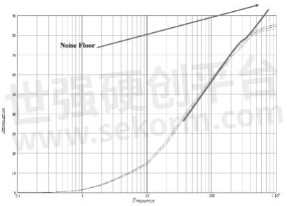
• The Noise Floor graph below shows attenuation still increasing at 80db. The Noise Floor is the value at which the connector will not exceed. Typically 75 –85db. This is limited by capacitor performance, source and load impedance and ground resistance.
• Cross talk is the electrical ‘coupling’ and therefore ‘sharing of data’ between two Lines. This is worse on adjacent and parallel lines / conductors.
One of the main components of a filter connector is the capacitor. The capacitor consists of multiple layers of ceramic insulators and precious metal conductors. The ceramic part has unique ability to store charge. The amount of charge that a capacitor can store depends on its capacitance and the voltage applied. The capacitance depends upon two factors; the first is the composition of the insulator (better known as the dielectric). Every dielectric has an inherent ability to store charge when compared to vacuum. This ratio is called a dielectric constant (K). Air, for example, has a dielectric constant of about 1.0; mica has a dielectric constant of 6.0. In other words, mica can hold 6 times more charge than air. The dielectric materials used at Smiths Interconnect have dielectric constants of 95 (C0G) and 3000 (X7R). The second determining factor is geometry of the capacitor. For a simple single layer capacitor, the capacitance increases with increases in area. The capacitance can also increase with decreasing thickness.
The capacitor design is based on the customer’s requirements which are found on Smiths Interconnect’s Engineering drawing. There are four major guidelines when designing a particular capacitor array.
1. Design must be large enough to compensate for shrinkage.
2. Multi-capacitance arrays require multi screen designs.
3. High capacitance designs not to exceed certain number of layers.
4. High voltage designs must meet minimum fired thickness.
The capacitance is influenced by the number of active printed layers, the overlap area, and the layer thickness. There must be a balance between all three parameters to ensure and reliable and economical component. With each printed layer, precious metal is used which is expensive. The amount of overlapping area between the ground plane and positive pattern must be small enough to minimize alignment variations, which can lead to failure, yet large enough to minimize the number of printed layers required to obtain a particular capacitance target. Large overlapping areas can increase the distribution of capacitance between the population of holes within a part. This wide distribution may exceed customer’s specifications. Finally the layer thickness must be large enough to safely exceed the customer’s voltage requirements. If the layer thickness design is too large than more printed layers are needed, increasing the overall thickness, making the capacitor too thick to fit into the connector design. If the capacitor is too thin, it may be prone to cracking during processing. There will always be at least two screens used for any one ceramic design, the ground plane and positive pad. The ground plane provides the ground connection to the connector shell. The positive pad provides connection to the contact pins.
The increased sensitivity of electronic systems and mandated performance requirements such as RCTA DO-160 make transient protection paramount in system design today. Transient suppression built into the connector provides the most space efficient and effective method of protection against Electromagnetic Protection (EMP), Lightning, Nuclear EMP and voltage transients. The excess energy is shunted to ground at the connector interface before it can even enter the system.
With the advent of today’s high signal transmission speeds coupled with low-level operating voltages, a need for high speed EMP protection circuitry has arisen. Smiths Interconnect has developed a complete series of EMP products ideally suited for this need. Densely packaged and protected within the connector shell, Smiths Interconnect employs the use of low voltage TVS bi-polar diode connected in series to a parallel network of back-back rectifiers as shown in the schematic diagram.
TVS diodes are mounted inside the connector around the periphery of the insert arrangement. Standard “catalog” diodes are utilized as opposed to custom or downsized diodes to increase reliability and minimize cost. JANTX diodes can be supplied; however, Smiths Interconnect can prescreen diodes with component level testing and burn-in which eliminates infant mortality.
The connector shell dimensions vary with the quantity and type of diodes chosen, but generally fit within the outline defined by the mounting flange. Smiths Interconnect’s method of mounting the diodes can be incorporated into any connector type including, but not limited to MIL-DTL-38999, ARINC 600 and ARINC 404. Where required, transient protection can be combined with EMI/RFI filtering to provide maximum protection. The diodes as well as the EMI filter are packaged separately so that the construction of the connector remains modular. Therefore, individual diodes as well as the EMI filter can be removed or replaced without disassembling the connector.
- +1 Like
- Add to Favorites
Recommend
- Design Concepts for EMI/EMP Filter Connector
- Filter Basics about Different Approaches to Q Factor
- Switch Filter Banks for Agile RF Receiver Design in Radar
- How to Use the Different Frequency Dependencies to Manipulate Impedance and Create Various Filter Responses?
- Knowles Microstrip Filter Helps Your Thin Film RF Devices to Achieve the Best Performance
- Knowles Precision Devices Introduces the SFSW Series of Hermetic, Panel-Mount EMI Filters
- Planar Filter Technology for Millimeter Wave Applications
- Expanding Knowles‘ Filter Technology Offerings to Serve Low-Frequency Applications
This document is provided by Sekorm Platform for VIP exclusive service. The copyright is owned by Sekorm. Without authorization, any medias, websites or individual are not allowed to reprint. When authorizing the reprint, the link of www.sekorm.com must be indicated.
Integrated Circuits


Discrete Components


Connectors & Structural Components


Assembly UnitModules & Accessories


Power Supplies & Power Modules


Electronic Materials


Instrumentation & Test Kit


Electrical Tools & Materials


Mechatronics


Processing & Customization


