Correct Use of Power Filters

During the test, we often encountered such a situation: although the design engineer connected a power filter to the power line of the equipment, the equipment still could not pass the "conducted disturbance voltage emission" test, and the engineer suspected that the filtering effect of the filter was not good. Constantly replace the filter, still can not get the desired effect.
The reasons for analyzing the equipment exceeding the standard are nothing more than the following two aspects:
The harassment generated by the equipment is too strong
Insufficient filtering of equipment
For the first case, we can solve it by taking measures at the source of disturbance to reduce the intensity of disturbance, or increase the order of the power filter to improve the filter's ability to suppress disturbance. For the second case, in addition to the poor performance of the filter itself, the installation method of the filter also has a great influence on its performance. This is often overlooked by design engineers.
In many tests, we were able to get the device to pass the test by changing the way the filter was mounted. Below are some examples of the effects of common filter installation errors on filter performance.
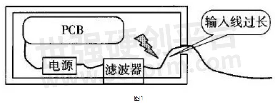
Input Cable Is Too Long
After the power cords of many devices enter the chassis, they go through a long wire to the input of the filter. For example, the power cord enters from the rear panel of the chassis, runs to the power switch on the front panel, and then goes back to the rear panel to connect to the filter. The installation position of the filter is far from the inlet of the power cable, resulting in the lead wire being too long (as shown in Figure 1).
Because the lead from the power inlet to the filter input is too long, the electromagnetic disturbance generated by the device is re-coupled to the power line through capacitive or inductive coupling, and the higher the frequency of the disturbance signal, the stronger the coupling, causing the experiment to fail.
Parallel Trace
To make the wiring inside the chassis beautiful, some engineers often bundle the cables together, which is not allowed for power cables. If the input and output lines of the power filter are routed in parallel or bundled together, due to the distributed capacitance between the parallel transmission lines, this wiring method is equivalent to connecting a capacitor in parallel between the input and output lines of the filter, which is a disturbance signal. A path is provided to bypass the filter, resulting in a significant performance degradation of the filter, or even failure at very high frequencies (as shown in Figure 2).
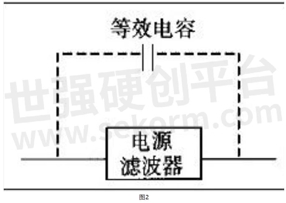
The size of the equivalent capacitance is inversely proportional to the wire distance and proportional to the length of the parallel traces. The larger the equivalent capacitance, the greater the impact on the filter performance.
Ground and Case
This situation is also relatively common. When many engineers install the filter, the connection between the filter housing and the chassis is poor (with insulating paint); at the same time, the ground wire used is long, which will lead to the deterioration of the high-frequency characteristics of the filter and reduce the filtering performance.
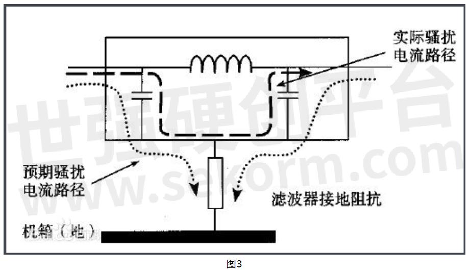
Due to the long ground wire, the distributed inductance of the wire cannot be ignored at high frequencies. If the filter is well connected, the interfering signal can be directly grounded through the housing. If the connection between the filter housing and the chassis is poor, it is equivalent to there being a distributed capacitance between the filter housing (ground) and the chassis, which will cause the filter to have a high ground impedance at high frequencies, especially in the case of distributed inductance. Near the frequency at which the distributed capacitance resonates, the ground impedance tends to be infinite.
Influence of poor filter grounding on filter performance: Due to the poor grounding of the filter, the grounding impedance is large, and some disturbance signals can pass through the filter (as shown in Figure 3). To solve the poor overlap, the insulating paint on the chassis should be scraped off to ensure a good electrical connection between the filter housing and the chassis.
In this installation method, the housing of the filter is in good contact with the chassis, which can block the opening of the power cord on the chassis and improve the shielding performance of the chassis; in addition, the input and output lines of the filter are isolated by the chassis shielding, eliminating the disturbance coupling between the input and output lines and ensuring the filtering performance of the filter.
- +1 Like
- Add to Favorites
Recommend
- Selection and Use of Filters
- The Primary Functions and Purposes of Filters
- Knowles‘ Microstrip Filters Offer a High Repeatability and Temperature Stability from -55℃ to 125℃
- What Are the Differences Between Inverter Filters and Reactors?
- Planar Filters Continue to Advance
- P-DUKE MCF Series Highly Integrated DC/DC Front-end Filters Accepting 9-36Vdc Input Voltage for Military and Rolling Stock Applications
- Are X-Band Lowpass RF Filters right for you?
- Unleashing the Potential Made in China: The Power of Custom Type Power Series
This document is provided by Sekorm Platform for VIP exclusive service. The copyright is owned by Sekorm. Without authorization, any medias, websites or individual are not allowed to reprint. When authorizing the reprint, the link of www.sekorm.com must be indicated.
Integrated Circuits


Discrete Components


Connectors & Structural Components


Assembly UnitModules & Accessories


Power Supplies & Power Modules


Electronic Materials


Instrumentation & Test Kit


Electrical Tools & Materials


Mechatronics


Processing & Customization


