The Basics of Electrical Properties and How Those Properties Impact Some of the Key Components in a Circuit

To help customers with filter selection, Knowles generally provide a lot of information on what our filters can do. But in this new Filter Basics Series, Knowles is taking a step back to cover some background information on how filters do what they do. Regardless of the technology behind the filter, there are several key concepts that all filters share that Knowles will dive into throughout this series. By providing this detailed fundamental filter information, Knowles hopes to help you simplify your future filtering decisions.
To kick-off this series, this post breaks down the basic properties impacting capacitor and inductor performance including resistance, capacitance, inductance, and impedance.
Every wire and every trace used for conducting signals on a printed circuit board (PCB) has elements of resistance, capacitance, and inductance. Since these parameters are often invisible, to truly understand each of these electrical properties, it is sometimes helpful to look at some more common physical analogies.
Let’s start with resistance. The mechanical analogy we can use for demonstrating resistance is friction. Figure 1 illustrates resistance, because as the person tries to pull the mass sitting on the ground, the ground causes friction and impedes this person’s attempt to move the mass.
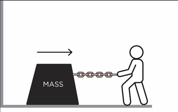
Figure 1. The friction caused by the ground impedes this person’s ability to pull the mass along the ground.
Next, let’s look at inductance, which is defined as the property of a wire or trace to resist any change in electrical current flowing through it and is sometimes referred to as electromagnetic inertia. If we continue with our example above, just like a mass will resist a change in velocity due to inertia, inductance will make a circuit resist current changes (Figure 2).
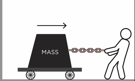
Figure 2. In this illustration, resistance was reduced by placing the mass on the wheeled platform, but the mass still has inertia when the person tries to move it.
When it comes to capacitance, or the ability to store an electric charge, a good way to think about the capacitor is in terms of a spring, which stores energy as it is expanded (Figure 3).
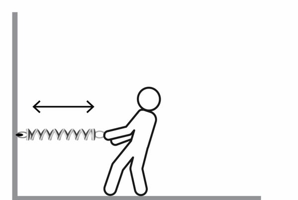
Figure 3. As the person pulls the spring, it stores energy that is used once the person releases the spring.
To put some of these concepts together, let’s look at a LC circuit, which is also known as a resonant, tuned, or tank circuit. LC circuits consist of an inductor (L) and a capacitor (C) and are most commonly used for generating signals at a particular frequency or picking out a signal at a specific frequency from a more complex signal. LC circuits oscillate with minimal damping, making resistance as low as possible. This can be illustrated by combining the examples shown in Figures 2 and 3. As shown in Figure 4, the spring will allow the mass on wheels to bounce back and forth, or oscillate, after it is pulled in one direction and then released by the person.
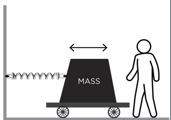
Figure 4. Once the person moves the mass on wheels and releases it, the mass will oscillate since it is attached to the spring.
A Brief Overview of Ohm’s Law and Impedance
Now, let’s look at how to predict a signal’s behavior within a circuit as electrical properties change when different voltages and currents are applied to a circuit. The formula used for this is known as Ohm’s Law:
Voltage (V) = Current (I)*Resistance (R)
Simply put, Ohm’s Law states that electric current is proportional to voltage and inversely proportional to resistance since resistance hinders the flow of current in the circuit. Ohm's Law calculated with this formula works well for resistors in DC circuits, but current-voltage relationships in AC circuits need to be modified to account for impedance, which is basically like resistance but for AC at a given frequency. This can be done by adjusting the formula above as follows:
V = I* Impedance (Z)
Putting it All Together: Defining Capacitors and Inductors
At a very basic level, a circuit can be made using a capacitor and an inductor. A capacitor impedes changes in voltage, with impedance decreasing with frequency, by storing energy in an electric field to preserve voltage (Figure 5).
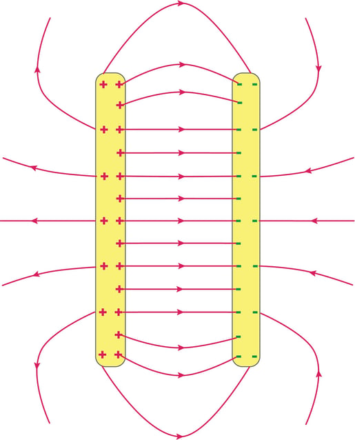
Figure 5. An illustration of how a capacitor stores energy between its two plates.
The impedance of the capacitor at different frequencies can be calculated using the following equation:
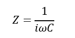
Z = Impedance, Omega = Angular Frequency, i is the imaginary number since we are using complex numbers here, and C = Capacitance.
This formula shows that as C increases, Z decreases, or for a given capacitance impedance will decrease with frequency.
Similarly, inductors impede changes in current, with impedance increasing with frequency, and store energy in a magnetic field to preserve current across the circuit (Figure 6).
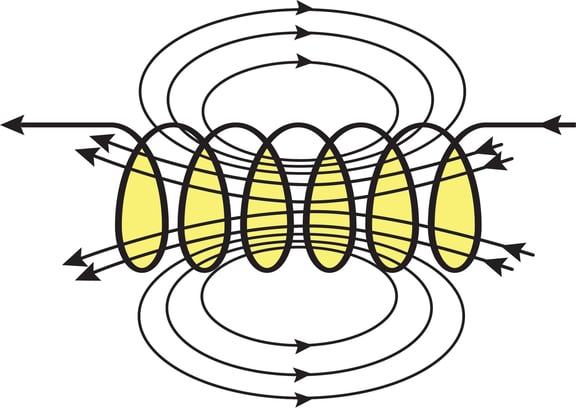
Figure 6. An illustration of how an inductor stores energy in its magnetic field.
The impedance of the inductor at different frequencies can be calculated using the following equation:
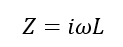
L = Inductance
Furthermore, we can see the different forms of impedance and the relationship to frequency below for each of the ideal lumped circuit elements.
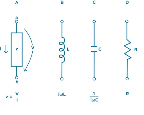
Figure 7. Using a form of Ohm’s Law where Impedance = Voltage/Current, we can calculate how impedance will impact each of these lumped circuit elements at different frequencies.
L and C Working Together: The LC Tank Circuit
As we just discussed, capacitors store energy in an electric field and impede changes in voltage while inductors store energy in a magnetic field and impede changes in current, with the impedance of both components changing with frequency. When put together in a circuit, capacitors and inductors have energy bouncing back and forth, or oscillating, as shown in the spring/wheel contraption in Figure 4, to power the circuit. The right combination of capacitance and impedance determines the frequency where the energy oscillates, which is known as the resonant frequency.
To demonstrate how this occurs, let’s walk through the steps of how an LC circuit functions and what happens when it is operating at its resonant frequency.
Step 1: We charge the capacitor by hooking it up to a battery. By doing this, the charge, and corresponding electric field as shown in Figure 5, stored in the capacitor increases over time. Energy stored in the capacitor will be ½*CV^2
Step 2: Once we think we have enough energy stored in the capacitor we can disconnect the battery. Now we have a charged capacitor.
Step 3: We hookup the capacitor to another circuit that contains an inductor. Without the original voltage applied from the battery, the capacitor will discharge energy into the circuit, creating a current flow. Therefore, the energy originally stored in the capacitor is dumped into the circuit.
Step 4: A current flowing in an inductor causes a magnetic field to grow around the inductor as shown in Figure 6. This stores energy in the inductor, equal to ½*LI^2
Step 5: Eventually, the capacitor is discharged and current stops flowing. This causes the magnetic field around the inductor to collapse, dumping the energy back into the circuit. As we already know, a changing magnetic field around an inductor creates a voltage, and this voltage causes current to flow into the capacitor again, charging it back up. An example LC circuit is illustrated in Figure 8.
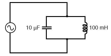
Figure 8. An illustration of a resonant tank circuit hooked up to an AC voltage. Source.
Since LC circuits have very little loss due to resistance, these circuits are commonly used in many components for signal processing and communication systems, including filters.
Now that we’ve covered the basics of electrical properties and how those properties impact some of the key components in a circuit.
- +1 Like
- Add to Favorites
Recommend
- Filter Basics about Different Approaches to Q Factor
- Switch Filter Banks for Agile RF Receiver Design in Radar
- How to Use the Different Frequency Dependencies to Manipulate Impedance and Create Various Filter Responses?
- Knowles Precision Devices Introduces the SFSW Series of Hermetic, Panel-Mount EMI Filters
- Knowles Microstrip Filter Helps Your Thin Film RF Devices to Achieve the Best Performance
- Planar Filter Technology for Millimeter Wave Applications
- Expanding Knowles‘ Filter Technology Offerings to Serve Low-Frequency Applications
- What is Filter Shape Factor and Selectivity?
This document is provided by Sekorm Platform for VIP exclusive service. The copyright is owned by Sekorm. Without authorization, any medias, websites or individual are not allowed to reprint. When authorizing the reprint, the link of www.sekorm.com must be indicated.
Integrated Circuits


Discrete Components


Connectors & Structural Components


Assembly UnitModules & Accessories


Power Supplies & Power Modules


Electronic Materials


Instrumentation & Test Kit


Electrical Tools & Materials


Mechatronics


Processing & Customization


