Sunlord Three-line CMC Coil SDMM0906 Series for MIPI C-PHY v1.0

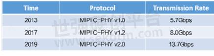
In response to the growing demand for data transferred from smartphone cameras and displays, the MIPI Consortium launched the C-PHY protocol in 2013 with higher transmission rates and lower device costs. Currently, some vendors are using MIPI C-PHY, and it may become a mainstream smartphone application in the future.
Table.1
MIPI C-PHY is a complex transmission line made up of three lines. It uses an embedded clock with up to 9-pin configuration for greater space saving. C-PHY determines the clock signal using the difference between three signal lines at 3/4V, 1/2 V, and 1/4V, respectively. Three lines have different states at the same time, so they have six different states, which are represented by ± X, ±y, and ± Z in the protocol. The state switch represents a transfer cycle.
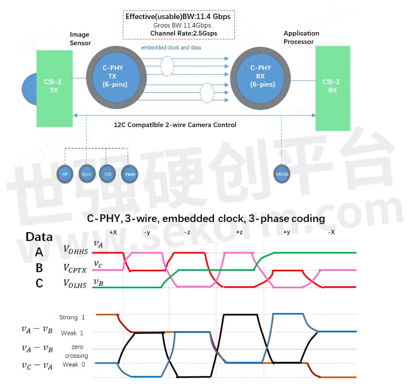
Fig.1
In the MIPI C-PHY v2.0 protocol, the transmission rate of a group of differential lines is as high as 13.7Gbps. The improvement of the transmission rate brings more high-frequency common mode noise interference, and a common mode choke coil is an effective way to solve the high-frequency common mode interference. The general differential transmission line is composed of two lines, which can be used to filter high-frequency noise with a two-line CMC coil. MIPI C-PHY is a complex transmission line consisting of three lines. If a two-line common mode choke coil is used, the number of devices will be increased, the common mode noise suppression effect is not good and the transmission waveform become disorder. MIPI C-PHY uses a three-line common mode choke coil coupled with three lines inside the magnet to effectively suppress common mode noise without affecting signal transmission.
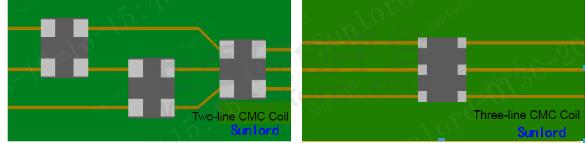
Fig.2
MIPI C-PHY v1.0 Three-line CMC SDMM0906 Series
Product size and equivalent circuit
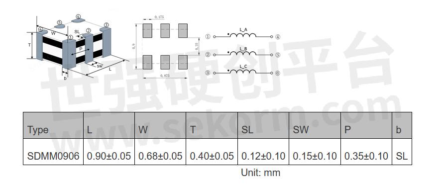
Fig.3
Features
Multi-layer and multi-loop structures to achieve high-impedance products
Effective for suppressing common mode noise at high frequency
Mature product technology platform, automatic production
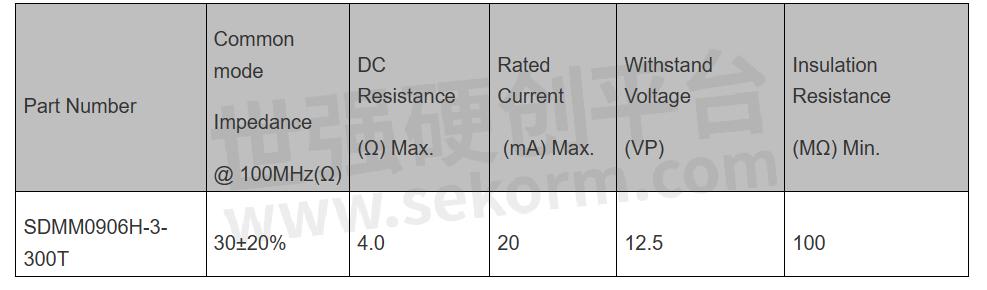
Electrical properties
SDMM0906H Series
Table.2
Insertion loss vs. Frequency (SDMM0906H-3-300T)
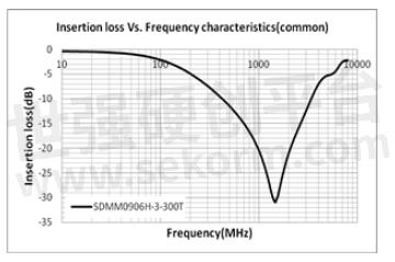
Fig.4
Insertion loss vs. Frequency (SDMM0906H-3-300T)
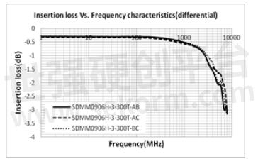
Fig.5
Impedance vs. Frequency (SDMM0906H-3-300T)

Fig.6
- +1 Like
- Add to Favorites
Recommend
- Sekorm Became an Authorized Distributor of Sunlord
- High-temperature Resistant and Anti-sulfur! Sunlord A*Z_H2T Series High-reliability Ferrite Beads
- Small but Powerful!Sunlord High Q Value 008004 (inch) Size Multilayer RF Inductor Released—HQ0201Q Series
- High-current Ferrite Beads for Audio Devices and GaN Fast Charging—MZPA Series from Sunlord
- Sunlord Newly Developed a Ceramic Dielectric Filter-VFCF Series,Which Covers the Sub-6G Frequency Band of Domestic 5G Base Stations
- Sunlord Developes High-performance of MWPU Series Power Inductor for Wearables
- Sunlord High Power Reactors UU Series Provide the Improved Performance by More Than 10% for PV Energy Storage
- Sunlord developed AMWPB Series Wire Wound SMD Power Inductors for Automotive combined with the BASE card wire laser welding process
This document is provided by Sekorm Platform for VIP exclusive service. The copyright is owned by Sekorm. Without authorization, any medias, websites or individual are not allowed to reprint. When authorizing the reprint, the link of www.sekorm.com must be indicated.
Integrated Circuits


Discrete Components


Connectors & Structural Components


Assembly UnitModules & Accessories


Power Supplies & Power Modules


Electronic Materials


Instrumentation & Test Kit


Electrical Tools & Materials


Mechatronics


Processing & Customization


