Learn About Power Divider

The Power Divider is a device that divides the power of one input signal into two or more outputs with equal or unequal energy, and can also conversely combine the energy of multiple signals into one output when it is called a combiner.
A certain degree of isolation should be guaranteed between the output ports of a power divider. A power divider is also called an over-current divider. There are two types: Active Divider and Passive Divider. It can evenly distribute one signal into several outputs.
Generally, each channel has a few dB attenuations. The signal frequency is different, and the attenuation of the divider is also different. In order to compensate for the attenuation, a passive power divider is made after adding an amplifier.
The technical parameters of the power divider include frequency range, withstand power, distribution loss from the main circuit to branch circuit, insertion loss between input and output, isolation between branch circuit ports, voltage standing wave ratio of each port, etc.
1.Frequency Range:
This is the working premise of various RF/microwave circuits, and the design structure of the power divider is closely related to the working frequency. The operating frequency of the allocator must be clarified first before the following design can be carried out.
2.Withstand power:
In a high-power divider/combiner, the maximum power that circuit components can withstand is the core indicator, which determines what form of the transmission line to be used to achieve the design task.
Generally, the sequence in which the transmission line withstands power from small to large is the microstrip line, strip line, coaxial line, air stripline, and air coaxial line.
The transmission form should be selected according to the design task.
3.Split Loss:
The distribution/split loss from the main circuit to the branch circuit is essentially related to the power distribution ratio of the power divider. For example, the distribution loss of the Bisection Power Divider is 3dB, and the distribution loss of the Quarter Power Divider is 6dB.

4.Insertion Loss:
The insertion loss between the input and output is due to factors such as the unsatisfactory medium or conductor of the transmission line. And the loss caused by the VSWR at the input also needs to be considered in the design.
5.Isolation:
The isolation between split ports is another important specification of the power splitter. The power of each branch port can only be from the main port, not from other neighboring ports. This requires sufficient isolation between the branch ports.
6.VSWR
The smaller the voltage standing wave ratio of each port, the better.
The common use of the power divider is to connect multiple satellite receivers. It is used to divide the input satellite IF signal into several outputs equally.
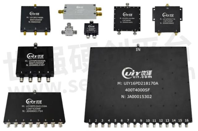
Here are the common types of Power Dividers/Power Splitters
2-Way Power Divider
3-Way Power Divider
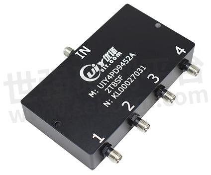
4-Way Power Divider
8-Way Power Divider
16-Way Power Divider
Choose a power divider according to the number of connected receivers. If two receivers are connected, 2-way power splitters are used, and four receivers are connected to 4-way power splitters.
- +1 Like
- Add to Favorites
Recommend
- Installation of UIY Surface Mounting Isolator/Circulator
- UIY Released New 180° 3dB UIY2T2HC4040A, Operating Over 6-18GHz Ultrawide Band, Insertion Loss Less Than 1.5dB
- UIY INC. Exhibits at 2024 IMS Washington D.C. 18th~21th June
- 5 Clues Help Understanding the DBS Band
- Things You Need to Know About Combiner and Duplexer
- Frequency Bands Suitable for Satellite Communications
- Microstrip Isolator/Circulator Mounting Instruction Manual
- Installation Instruction of Drop In Isolator & Circulator
This document is provided by Sekorm Platform for VIP exclusive service. The copyright is owned by Sekorm. Without authorization, any medias, websites or individual are not allowed to reprint. When authorizing the reprint, the link of www.sekorm.com must be indicated.
Integrated Circuits


Discrete Components


Connectors & Structural Components


Assembly UnitModules & Accessories


Power Supplies & Power Modules


Electronic Materials


Instrumentation & Test Kit


Electrical Tools & Materials


Mechatronics


Processing & Customization


