The Pros and Cons of Different Filter Structures

The LC filter is a filter composed of appropriate capacitors and inductors. It could be designed to realize low-pass, band-pass, high-pass, and band-stop filters.
Pros: Small size, low cost, long parasitic passband
Cons: The insertion loss is high, the out-of-band selection performance is poor, and the power capacity is small.
In addition, the inductance in the LC filter adopts the method of winding coils, so it is difficult to realize the inductance for high-frequency filtering. Therefore, LC filters are usually used to design filters for frequencies below 4GHz.

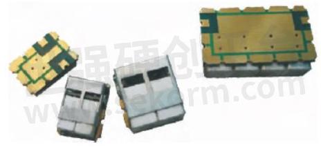
SAW/BAW Filters
The SAW Filter uses the method of converting electrical energy into surface acoustic waves, and uses the acoustic resonance effect to achieve filtering. The surface acoustic wave filter is characterized by a miniature size, and a higher Q value compared to the LC filter, and it adopts semiconductor technology, which is suitable for mass production.
A filter around 800MHz is about the size of a 0805 capacitor. The disadvantage is that the power capacity is small, it is not suitable for small-batch customized products, and it takes a long time and high cost of research and development. SAW filters are commonly used in end-consumer electronics.
Helical/Spiral filters
The spiral filter is a filter with semi-lumped parameters, which uses the self-resonance of the spiral inductor placed in the cavity to realize the resonator, and realizes the coupling through the spatial magnetic field of the adjacent resonators.
Pros: It is a comparatively smaller size, and the Q value and power capacity are higher than that of LC filters.
Cons: it is difficult to realize broadband and the inductance of high-frequency parts is not easy to realize.
Helical/Spiral filters are usually used in occasions with 20% relative bandwidth below 500MHz, 100W average power, and insertion loss are required under certain levels.
The dielectric filter is a semi-lumped filter realized by a dielectric-filled quarter-wavelength short circuit or a half-open circuit.
Pros: the Q value is higher than that of the LC filter, and a filter with a higher frequency can be realized rather than the LC filter.
Cons: the parasitic band is relatively close, and the resonator needs to be customized.
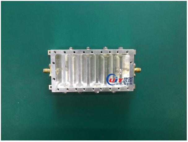
Cavity Filter
The cavity filter is one of the most important types in the filter family, and it is widely used in the front end of the radio frequency system. Among them, the transmitting back-end (after the power amplifier) and the receiving front-end (before/after the LNA) cannot be replaced by other types of filters.
Cavity Filters can be divided into: Comb, Interdigitated, Waveguide cavity, Dielectric cavity, etc. Among them, the comb structure can realize the filter required by various indicators within 200MHz to 15GHz, and the bandwidth is within 30%; the interdigitated filter can realize the filter within 800MHz to 26GHz, and the bandwidth is within 40%.

Waveguide cavities are often used to realize filters with a relative bandwidth of 15% within 8GHz to 60GHz. Dielectric Cavity Filters are usually used to realize filters within 2GHz to 18GHz and relative bandwidth within 0.1%~1.5%.
Compared with other cavity filters, the biggest advantage of the Comb Cavity Filter is to realize the far parasitic passband characteristics with a relatively wide bandwidth. At the same time, cavity filters can achieve the minimum size at the same bandwidth and the same out-of-band suppression comparing to other types. However, due to the presence of loading capacitance in the comb cavity, the power capacity would be relatively low.
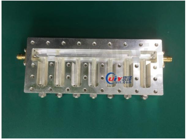
The biggest feature of the interdigital filter is that it can achieve broadband. If redundant resonant rods are used, considering that the machine is linear, its relative bandwidth can usually be as wide as 60%. At the same time, in the K-band, it is hard to process the broadband comb filter in a CNC machine and the debugging screw cannot be placed, so the interdigitated structure is usually used under this condition.
Compared with the comb structure, the parasitic passband of the interdigitated structure is closer, and its parasitic passband is usually around 1.8F0. Under the same size, the interdigital filter has a larger power capacity than the comb filter.
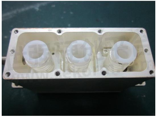
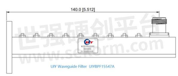
The Waveguide Cavity Filter has the characteristics of high Q, high power capacity, etc., but the filter of the waveguide cavity is generally large in size. When the requirement of insertion loss is not too high, it is generally realized by using an interdigitated or comb filter.
However, the waveguide cavity is still one of the better choices for narrow-band filters with high requirements of insertion loss regardless of the size requirement.
Generally, under the same technical index, the insertion loss of a waveguide cavity filter is about half of that of interdigitated or comb filter. In addition, the power capacity of waveguide cavity filters is about an order of magnitude higher than that of interdigitated filters and comb filters, so waveguide cavity filters are often used at high-power radar antenna feeds.
The Dielectric Cavity Filter has the highest Q value in the filter, and its Q value is about 2 to 5 times that of the waveguide cavity, and it is about an order of magnitude higher than the Q value of the comb-shaped and interdigitated filter.
However, the dielectric cavity filter is large in size, the out-of-band parasitic band is very close, and the bandwidth cannot be made very wide. Therefore, the dielectric cavity filter is usually used in occasions where the relative bandwidth is lower than 1%, but the loss requirement is high.
Filters with planar structures are usually realized by microstrip, stripline, and suspended stripline. There are few conventional applications of microstrip and stripline filters and relatively more applications of suspended striplines.
The reason is that suspended striplines have better parasitic characteristics and are easy to realize distributed capacitance in structure. Therefore, suspended stripline filters are suitable for ultra-wideband (relative bandwidth greater than 50%) band-pass filters or high-pass filters.
There are also many applications for low-pass filters with suspended microstrips, mainly because the parasitic passbands of suspended microstrip low-pass can be used as to 3~5 times Fc.
Summarize:
Filters are essential and critical components of wireless communication systems.
There are many types of filters, and each filter has different performance characteristics. Therefore, when selecting a filter, it is usually necessary to comprehensively consider the actual installation environment and customer requirements of filter performance to make a correct, effective, and reliable choice.
When the customer has a vague concept of the filter index, it is usually necessary to ask the customer about the size, insertion loss, out-of-band frequency that needs to be rejected, the rejection value, and power capacity. According to the information provided, the type of filter can be recommended or designed.
- +1 Like
- Add to Favorites
Recommend
- Installation of UIY Surface Mounting Isolator/Circulator
- UIY Released New 180° 3dB UIY2T2HC4040A, Operating Over 6-18GHz Ultrawide Band, Insertion Loss Less Than 1.5dB
- UIY INC. Exhibits at 2024 IMS Washington D.C. 18th~21th June
- 5 Clues Help Understanding the DBS Band
- Things You Need to Know About Combiner and Duplexer
- Frequency Bands Suitable for Satellite Communications
- Microstrip Isolator/Circulator Mounting Instruction Manual
- Installation Instruction of Drop In Isolator & Circulator
This document is provided by Sekorm Platform for VIP exclusive service. The copyright is owned by Sekorm. Without authorization, any medias, websites or individual are not allowed to reprint. When authorizing the reprint, the link of www.sekorm.com must be indicated.
Integrated Circuits


Discrete Components


Connectors & Structural Components


Assembly UnitModules & Accessories


Power Supplies & Power Modules


Electronic Materials


Instrumentation & Test Kit


Electrical Tools & Materials


Mechatronics


Processing & Customization


