CAN XL and 10BASE-T1S——Dataline Performance of Two New Actors in The Networking Arena
Higher, faster, further, slower
In our daily live, sport, technology development, everything is about getting things better, faster or move things further. It is very hard to remember that inventing something slower than before was celebrated as an innovation, but this is exactly what has happened to Automotive Ethernet.
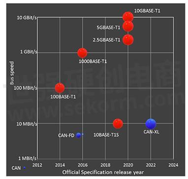
Figure 1: Ethernet and CAN specification roadmap
First 100MBit/s and 1000MBit/s versions were developed and introduced to the market successfully with physical layers that allows auto-negotiation for simplified system integration. Towards the end of the last decade, an automotive Ethernet version supporting just 10MBit/s was developed with a physical layer not compatible to the 100MBit/s and 1GBit/s version; a clear downgrade in performance.
The step back to an older topology style and lower speed was requested by OEMs to close the gap in performance for lower speed grade applications in terms of cost per Ethernet port. CAN FD at that point in time was supporting 2MBit/s and got improved over time to 5MBit/s. The community around CAN also saw the need for higher bandwidth and longer payload and started a development of an improved CAN standard called CAN XL.
This first part is giving a brief overview about CAN XL and 10MBit/s Ethernet, what are the differences between them.The second part will describe potential use-cases and what the implications to hardware and software will be.
10MBit automotive protocols
Even CAN XL and 10BASE-T1S are developed in different standardization bodies, with wide support from the industry, the process is pretty much the same.
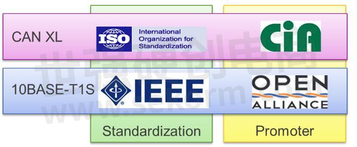
Figure 2: Standard development scheme
The foundation of the technical work for CAN XL was done in CAN in Automation (CiA). After stabilizing the document it was handed over to ISO to create an international standard. This process is still ongoing and expected to finish in 2023 with an approved international standard. The CiA will continue to promote the CAN standard as technical committee and user alliance.
The Ethernet specifications are owned and maintained by the IEEE. All the standardization work was done inside a working group that created 2019 a draft for incorporation into the IEEE 802.3 main standard. Because the IEEE is an industry independent organization, the OPEN Alliance takes care for extending the specification for automotive requirements. For long term maintenance of OPEN Alliance specifications also the ISO is involved.
· CAN XL – higher speed, more payload, and additional features
Although CAN XL is providing full backward compatibility to CAN FD, the frame format was extensively updated. This post Renesas will cover the main differences and outline the intention of new fields.
CAN XL follows the concept of CAN FD having a low speed arbitration phase (up to 1MBit/s) and a high speed data phase. The CAN XL data phase bit time is specified to reach up to 10MBit/s. Another key characteristic of CAN XL is that the payload length can be up to 2048 bytes. Further, CAN XL is fully backward compatible to CAN FD.
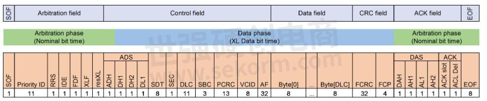
Figure 3: CAN XL frame format
Figure 3 shows the CAN XL frame format, names the different field regions, and indicates where the nominal bit time is used and where the high-speed bit time starts. Following the key-changes are briefly explained – as you see, nearly everything was updated.
Priority ID – This 11 bit long field is what was previously called the “base identifier”. CAN XL only supports 11 bit in this first arbitration field.
IDE – Simply because identifier extensions are not supported, this bit is always transmitted as dominant bit.
XLF, resXL – These two bits (XLF being recessive and resXL being dominant) code that the following frame is a CAN XL data frame.
ADS – The “arbitration to data sequence” is the point where the switch from nominal- to XL Data bit time happens. Compared the CAN-FD where the change was done in a single bit, the transition takes longer in CAN XL to increase the robustness of this sensitive process allowing the Transceiver to change to the FAST Mode where the TX nodes can operate in push/pull mode.
SDT – The “service data unit type” is an upper layer information to describe the type of the payload. This field is comparable to the EtherType in Ethernet protocol. SDT are defined by CiA 611-1.
SEC – This bit indicates if the frame holds simple or extended content in the payload and is provided from the upper layer.
DLC – The data length code field has the same meaning as in previous version. With this 11 bit long field, a data field from 1 byte to 2048 bytes is indicated.
SBC – The stuff bit count field gives information about the number of dynamic stuff bits in the arbitration field. In a later article we will go into details of the stuff bit rules. This value will be calculated by the protocol controller.
PCRC – The preface CRC field is a CRC calculated over most of the bits from the arbitration field and control fields explained so far. The aim is to get additional protection over the header information.
VCID – The “Virtual CAN network ID” is supposed to support virtualization on the CAN bus, like the concept of VLAN in Ethernet networks.
AF – The acceptance field, also provided by the upper layers, are additional 32 bit for frame classification and can be seen as compensation to the reduced priority identifier field.
Data field – In this field the actual payload is transmitted as provided by the upper layer where the bytes are numbered from 0 to DLC.
FCRC – The frame CRC is calculated over all dynamic bits seen so far
FCP – The format check pattern allows a receiver to confirm that he is still in synchronization on the bitstream with the transmitter and announces the end of the CAN XL data phase. This is a very simplistic explanation of this field.
DAS – In the data to arbitration sequence the bit rate is switched from XL Data bit time to the nominal bit time.
ACK/ EOF – The frame is concluded with the known acknowledge slot and EOF sequence which are not changed in format.
On the media access scheme there were no changes compared to previous CAN versions and CAN XL still follows the CSMA/CR principle.
· 10BASE-T1
After spending many words on CAN XL let’s have a look to 10MBit automotive Ethernet, to be precise, the 10 MBit/s single pair Ethernet (SPE) as defined in the IEEE 802.3cg. The MAC layer protocol of 10MBit SPE does not differ from any other Ethernet protocol and need no further explanation.

Figure 4: Scope of IEEE 802.3cg [4]
Instead, the IEEE defined a physical layer meeting the demand for automotive industry in terms of robustness, implementation cost and cabling. The result are two different physical layers with different application targets.
10BASE-T1L – This is the “long reach” variant of 10MBit/s SPE allowing a cable length of up to 1000 meters. This point-to-point variant is out of scope for automotive applications but may be used for trucks, trains, and other vehicular technologies.
10BASE-T1S – This is the “short reach” variant with cable length of up to 25 meter and allows a bus topology with 10cm stubs. To avoid collisions on the shared bus topology the standard defines an optional reconciliation sublayer called PLCA (Physical Layer Collision Avoidance).
PLCA – Target of PLCA is to improve the existing collision detection mechanism in Ethernet (CSMA/CD) on a multidrop (bus) topology in terms of throughput, latency, and fairness. It is important to know that this “arbitration” takes purely place on PHY level, the MAC does not take any role in the following described process.
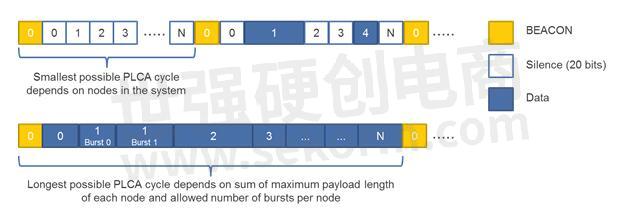
Figure 5: PLCA cycle example [2]
In a PLCA system, each PHY is assigned with a unique PHY ID in the range from 0 to 255. The PHY with the ID 0 is the PLCA coordinator. Each PHY on the bus is aware about the number of PHYs. PLCA uses a round robin scheme whereby each round is triggered by the PLCA coordinator sending a BEACON. Each participant in the PLCA scheme, including the coordinator have a single transmit opportunity after the BEACON in the order of PHY IDs.
A transmit opportunity is just an opportunity. If a node has nothing to transmit, the next PHY in the system gets his opportunity after a timeout period. If a node has a transmission pending it is allowed to start transmitting a frame inside his transmit opportunity. If allowed by the system configuration, a node can also transmit more than one frame, so called bursts. They payload length of each message can be different.
This scheduling scheme avoids bus collisions and re-transmissions that lowers the usable bandwidth and guarantees fairness of transmit opportunities inside a system. On top of this PLCA mechanism, other shaping functions like Credit Base shaping or Time Aware Shaping can be enabled in the MAC layer.
Comparison between CAN XL and 10BASE-T1S – The winner is …
The winner is the user. Both protocols deliver a data rate that allows applications to transmit longer payload and achieve on the bus transmission speed close to 10Mbit/s. Even the media access schemes are different, let’s take two ways to compare.
· Datagram efficiency
Both protocols have overhead in the datagram in the form of header and trailer (e. g. addressing, protocol fields, CRC). In CAN XL the efficiency is further affected by stuff bits and different bus speeds during the arbitration phase and data phase.

Figure 6: Datagram efficiency comparison
Figure 6 plots the efficiency of a datagram over the payload by putting the amount of spend on overhead in relation to the time spend on payload bits.
CAN XL suffers from the slower arbitration phase and bigger header and more overhead bits. Running the arbitration phase at 1MBit/s instead of 500kBit/s improves the datagram efficiency significant for shorter frames. Someone may perfectly argue that in CAN XL the protocol type and acceptance fields are user-date and not overhead. This would bring CAN XL closer to the curve of 10BASE-T1S.
· Bus cycle efficiency
If we observe a PLCA cycle instead of a single datagram, the situation is changing.
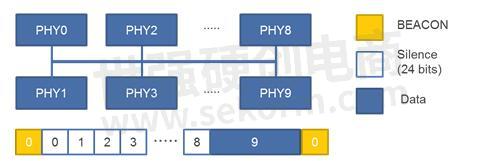
Figure 7: PLCA cycle example
Let’s assume a system configuration as shown in Figure 7 and assume that only PHY 9 has a pending transmission. In this case, the bus remains unused by 9 times the timeout period which we assume to 24 bits in this case. Plus, the additional time required by the BEACON, the efficiency changes as shown in Figure 8.
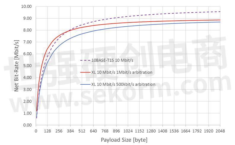
Figure 8: Bus cycle efficiency example
In CAN XL the bus efficiency is not reduced by waiting for any transmit opportunities, but still the idle times and EOF sequence needs to be considered. However, under typical operation conditions with 512bytes of payload, both protocols show same efficiency.
Conclusion and outlook
Both protocols are developed to handle requirements of new E/E architecture and provide the expected performance in the 10MBit/s region. Beside the here briefly explained protocol fields, there were several other enhancements in terms of usability on higher level protocols, e.g., considerations for security or power delivery.
The efficiency of protocols depends on the use-case, system configuration and usage of extended features. It is more a philosophical or strategic question which variant is preferred. From our perspective both protocols have the potential to be used in the same in-vehicle-network (IVN) in different applications.
- +1 Like
- Add to Favorites
Recommend
This document is provided by Sekorm Platform for VIP exclusive service. The copyright is owned by Sekorm. Without authorization, any medias, websites or individual are not allowed to reprint. When authorizing the reprint, the link of www.sekorm.com must be indicated.
Integrated Circuits


Discrete Components


Connectors & Structural Components


Assembly UnitModules & Accessories


Power Supplies & Power Modules


Electronic Materials


Instrumentation & Test Kit


Electrical Tools & Materials


Mechatronics


Processing & Customization


