Analysis of ZMM3V0 Zener Diode and Generating Square Waves Using a Zener Diode

In the vast family of electronic components, the Zener diode is an indispensable member, particularly in circuits requiring stable voltage output. The ZMM3V0, as a type of Zener diode, is widely used for its stable 3V output voltage and excellent performance. In this article, we will provide a detailed analysis of the ZMM3V0 Zener diode.
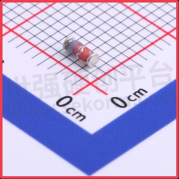
SLKOR Voltage Regulator Diode ZMM3V0 product photo
1. Zener Voltage and Its Range
The nominal Zener voltage of the ZMM3V0 is 3V, which is one of its most fundamental and crucial characteristics. This means that under normal operating conditions, the ZMM3V0 can provide a stable 3V output voltage. However, this Zener voltage is not fixed and can vary within a certain range, specifically between 2.8V and 3.2V. This range ensures that the ZMM3V0 can still provide a stable output voltage under different environmental and operating conditions, meeting the demands for voltage stability in electronic circuits.
2. Power Characteristics
Power is an important parameter for Zener diodes, determining the maximum current and voltage the component can handle. The power rating of the ZMM3V0 is 500mW, which means that under normal operating conditions, it can handle up to 500 milliwatts of power. This parameter ensures that the ZMM3V0 can operate stably within a circuit, while also reminding us not to exceed its power limit to avoid damaging the component.
3. Reverse Current (Ir)
The reverse current is the current that flows through the Zener diode when it is reverse-biased. For the ZMM3V0, the reverse current (Ir) is 4μA at a reverse voltage of 1V. This parameter reflects the performance of the ZMM3V0 under reverse bias conditions and provides important reference information for its use. In circuit design, we need to select appropriate circuit parameters based on the reverse current characteristics of the ZMM3V0 to ensure the stability and reliability of the circuit.
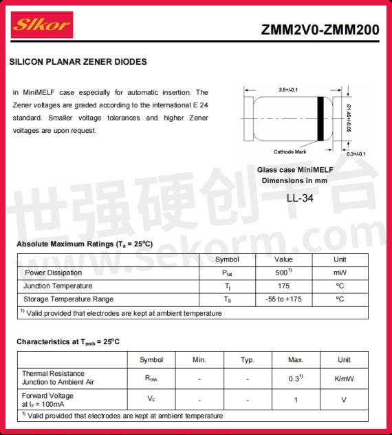
Slkor Voltage Regulator Diode ZMM3V0 specification
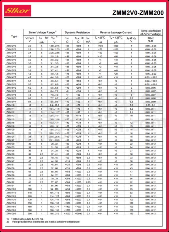
Parameters of Slkor Voltage Regulator Diode ZMM3V0
4. Application Fields
Due to its stable output voltage and excellent performance, the ZMM3V0 Zener diode is widely used in electronic circuit design. It is commonly used in circuits that require stable voltage output, such as power supply circuits, amplifier circuits, and protection circuits. In these circuits, the ZMM3V0 effectively stabilizes the output voltage, enhancing the circuit's performance and reliability.
5. Using Zener Diodes to Generate Square Waves
Circuit Design Considerations
● Choosing the Zener Diode:
Select a Zener diode with an appropriate Zener voltage, such as the ZMM3V0 (Zener voltage of 3V, range 2.8-3.2V).
Depending on the desired square wave amplitude, different Zener voltage values can be chosen.
● Reverse Connection and Series Configuration:
Use two Zener diodes and connect them in series with opposite polarities. This means connecting the anode of one diode to the cathode of the other.
This configuration allows the circuit to have Zener regulation during both positive and negative cycles of the input signal.
● Input Signal and Current Limiting Resistor:
Provide an input signal (such as a sine wave or triangle wave) and connect it to the two Zener diodes through a current limiting resistor (R1).
The current limiting resistor restricts the current passing through the Zener diodes, preventing damage to the diodes.
● Output Signal:
Take the output signal from the connection point between the two Zener diodes.
During the positive half-cycle of the input signal, one Zener diode is forward-biased and the other is reverse-biased and regulating.
During the negative half-cycle, the roles reverse, with the previously reverse-biased diode now forward-biased and vice versa.
● Adjusting the Output Waveform:
By adjusting the frequency and amplitude of the input signal and the resistance value of the current limiting resistor, you can control the frequency, amplitude, and duty cycle of the output square wave.
Note that due to the non-ideal characteristics of Zener diodes and other circuit components, the output waveform may not be a perfect square wave, but can be optimized by tweaking the parameters.
Example Circuit Configuration
Assume using two ZMM3V0 Zener diodes, with a Zener voltage of approximately 3V.
The input signal is a sine wave or triangle wave, connected through an appropriate current limiting resistor R1 to the two Zener diodes.
The output signal is taken from the connection point between the two Zener diodes and observed on an oscilloscope.
Cautions
The Zener voltage of the diodes, the frequency and amplitude of the input signal, and the resistance value of the current limiting resistor all affect the shape and characteristics of the output square wave.
In practical design, multiple trials and adjustments may be necessary to optimize the output waveform.
The choice of Zener diodes and other circuit components should be based on specific application requirements and environmental conditions.
- +1 Like
- Add to Favorites
Recommend
- The Voltage Regulator Diode ZMM3V9 Has a Maximum Power Dissipation of 500mW and a Stable Voltage Value of 3.9V
- The Voltage Regulator Diode ZMM3V6 with A Maximum Power Dissipation of 500mW and A Stable Voltage Value of 3.6V
- Analysis of the Production Process and Characteristics of ZMM3V3 Voltage Regulator Diode
- Slkor ZMM10: A High-Performance Zener Diode for Voltage Regulatio with A Maximum Power Dissipation of 500mW
- Slkor ZMM2V4: High-Performance Zener Diode for Medium-Voltage Applications with A Typical Zener Voltage of 2.4V
- How is the Delivery Efficiency of SLKOR?
- Slkor Participated in the 8th Qianren Summit of Dajia Yuan
- Has SLKOR Passed ISO14001?
This document is provided by Sekorm Platform for VIP exclusive service. The copyright is owned by Sekorm. Without authorization, any medias, websites or individual are not allowed to reprint. When authorizing the reprint, the link of www.sekorm.com must be indicated.
Integrated Circuits


Discrete Components


Connectors & Structural Components


Assembly UnitModules & Accessories


Power Supplies & Power Modules


Electronic Materials


Instrumentation & Test Kit


Electrical Tools & Materials


Mechatronics


Processing & Customization


