Wireless Module Electrical Performance Test Report:All Technical Indicators Have Reached the Standard Requirements

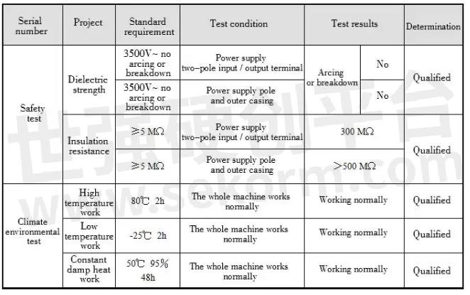
In order to better guarantee the product quality of Wireless modules, G-NiceRF sends the wireless modules it produces to the laboratory for inspection and testing. The inspection items include safety testing, climate and environmental testing, electromagnetic compatibility testing, etc. The specific test values of various technical indicators are as follows.
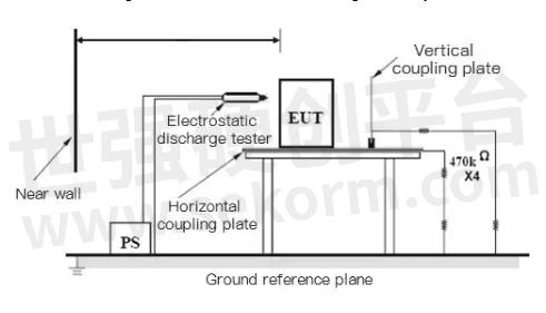
1. Electrostatic discharge test
Contact discharge: test method and standard requirements: the tested sample is in normal working condition, and the metal surface of the tested sample (select 4 sensitive points) is used for contact discharge with an electrostatic discharge instrument. Discharge voltage: 4kV, each sensitive Pointing is performed 20 times (10 times for positive and negative polarity), with an interval of 1S each time. Should meet performance criterion B.
Test result: meet the requirements
Air discharge: test methods and standard requirements: the tested sample is in normal working condition, and the non-metallic surface (including holes, seams, etc.) of the tested sample is air discharged with an electrostatic discharge instrument. The discharge voltage: 8kV, each Pointing is performed 20 times (10 times for positive and negative polarity), with an interval of 1S each time. Should meet performance criterion B.
Test result: meet the requirements
Connection diagram of electrostatic discharge test layout:
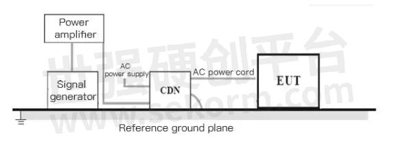
2. Radio frequency continuous wave conduction test
Test method and standard requirements: The sample under test is in normal working condition, and 80℅AM (1kHz) sinusoidal modulation signal is applied to the AC power terminal and signal terminal, the test voltage is 3V, and the frequency range is 0.15-80MHz. Should meet performance criterion A.
Inspection result: meet the requirements
Connection diagram of radio frequency continuous wave conduction test layout:
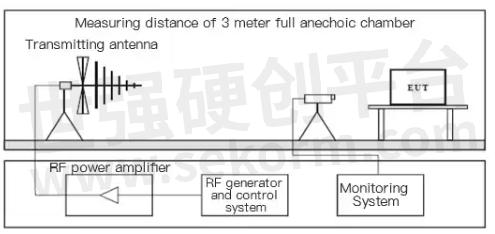
3. Radio frequency electromagnetic field test
Test method and standard requirements: The sample under test is in normal working condition, and 80℅AM (1kHz) sinusoidal modulation signal is applied to the AC power terminal and signal terminal, the test field strength is 10V/m, and the frequency range is 80-1000MHz. Should meet performance criterion A.
Inspection result: meet the requirements
Connection diagram of radio frequency electromagnetic field test arrangement:
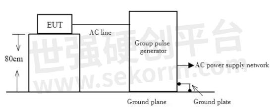
4. Electrical fast transient test
Power supply terminal: The test sample is in normal working condition, and the transient pulse generator is used to apply a pulse group of voltage 1.0kV and frequency of 5kHz to the AC power supply terminal of the test sample. , Application time: 1 time 1 minute. Should meet performance criterion B.
Signal terminal: Use the transient pulse group generator capacitive coupling clamp to apply a pulse group with a voltage of 0.5kV and a frequency of 5kHz to the signal terminal. The number of applications: positive and negative polarity 1 time, application time: 1 time 1 minute. Should meet performance criterion B.
Inspection result: meet the requirements
Electrical fast transient test layout connection diagram:
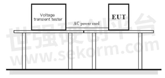
5. Voltage sag test
Detection method and requirements: The sample under test is in normal working condition, and the AC power port is input with 70% of the rated voltage with a voltage instantaneous interruption tester for 25 cycles. Should meet the performance criterion C.
Inspection result: meet the requirements
Detection method and requirements: The sample under test is in normal working condition, and the AC power port of the tester is used to input the rated voltage of <5% for 0.5 cycle. Should meet performance criterion B.
Inspection result: meet the requirements
6. Short-term voltage interruption test
Detection method and requirements: The tested sample is in normal working condition, and the AC power port of the tester is used to input a rated voltage of <5% for 250 cycles. Should meet the performance criterion C.
Inspection result: meet the requirements
Connection diagram of test arrangement for voltage sag and short-term interruption of voltage:
7. Surge test
Testing method and requirements: The test sample is in normal working condition, and the surge signal generator is used to apply the surge combined wave signal to the AC power terminal of the test sample. The number of applications: positive and negative polarity 5 times each, repetition rate: 1 Times/1 minute, applied voltage: line-line: 1kV; line-ground: 2kV. Should meet performance criterion B.
Inspection result: meet the requirements
Surge test layout connection diagram:

The above is the test report of G-NiceRF's wireless module products. All technical indicators have reached the standard requirements. Its good performance is obvious, and it is a high-quality wireless module.
- +1 Like
- Add to Favorites
Recommend
- What is the Role of the Wireless Module with a Shielding Cover
- Method to Improve the Transmission Distance of 433MHz Wireless Module
- Advantages Analysis of the Wireless Module in Industrial Automation Production
- Wireless Module: Factors Affecting Transmission Distance
- Reasons and Solutions for Wireless Module Verification Failure
- Product Advantages and Features of the Wireless Module
- The built-in Wireless Module of the Bicycle Smart Helmet Can Play Music
- Wireless Module Application in VR Headset Devices
This document is provided by Sekorm Platform for VIP exclusive service. The copyright is owned by Sekorm. Without authorization, any medias, websites or individual are not allowed to reprint. When authorizing the reprint, the link of www.sekorm.com must be indicated.
Integrated Circuits


Discrete Components


Connectors & Structural Components


Assembly UnitModules & Accessories


Power Supplies & Power Modules


Electronic Materials


Instrumentation & Test Kit


Electrical Tools & Materials


Mechatronics


Processing & Customization


