Features, Characteristics and User Guides of TVS Diodes

TVS DIODE Description
The transient voltage suppression diode TVS is an overvoltage protection device with bidirectional voltage stabilization characteristics and bidirectional negative resistance characteristics, similar to a varistor. It is used in various AC and DC power circuits to suppress instant overvoltage. When a surge pulse voltage occurs instantaneously in the protected circuit, the bidirectional breakdown diode can quickly undergo Zener breakdown, change from a high-resistance state to a low-resistance state, shunt and clamp the surge voltage, thereby protecting the components in the circuit. Damaged by momentary surge pulse voltage.
Feature
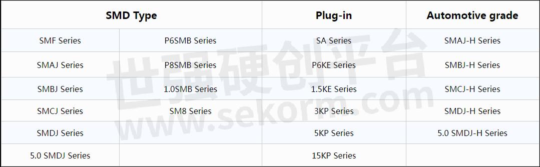
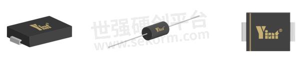
The response speed is extremely fast (ps level); the surge resistance ability is worse than that of discharge tubes and varistors. Its 10/1000μs wave pulse power ranges from 400W to 30KW, and the pulse peak current ranges from 0.52A to 544A; the breakdown voltage ranges from The series values from 6.8V to 550V are convenient for use in circuits with different voltages. Its packaging forms include axial lead type and patch type.
Product display
Characteristic
TVS tubes are divided into unidirectional and bidirectional (the letter after the unidirectional model is "A" and the bidirectional one is "CA"). The characteristics of the unidirectional TVS tube are similar to those of the Zener diode, and the characteristics of the bidirectional TVS tube are equivalent to those of two Zener diodes are connected in reverse series. Its main characteristic parameters are:
1. Reverse off-state voltage (cut-off voltage) VRWM and reverse leakage current IR: Reverse off-state voltage (cut-off voltage) VRWM represents the highest voltage at which the TVS tube does not conduct. At this voltage, there is only a small reverse leakage current. IR.
2. Breakdown voltage VBR: The voltage when the TVS tube passes the specified test current IT. This is the symbol voltage indicating that the TVS tube is conductive (the numbers in the P4KE, P6KE, and 1.5KE series models are the nominal value of the breakdown voltage, and others Series numbers are reverse off-state voltage values). The breakdown voltage of TVS tubes has an error range of ±5% (±10% without "A").
3. Pulse peak current IPP: The maximum peak current of the 10/1000μs wave that the TVS tube is allowed to pass through (the peak current of the 8/20μs wave is about 5 times). Exceeding this current value may cause permanent damage. In the SAme series, tubes with higher breakdown voltage allow smaller peak currents to pass through.
4. Maximum clamping voltage VC: The voltage present at both ends of the TVS tube when the pulse peak current IPP flows through it.
5. Pulse peak power Pm: Pulse peak power Pm refers to the product of the pulse peak current IPP of the 10/1000μs wave and the maximum clamping voltage VC, that is, Pm=IPP*VC.
6. Steady-state power P0: TVS tubes can also be used as zener diodes, and steady-state power must be used at this time. The steady-state power of each series is shown in the table below:
Pulse peak power Pm 400W 500W 600W 1500W 3000W
Steady state power P0 1W 3W 5W 6.5W 8W
7. Inter-electrode capacitance Cj: Like the varistor, the inter-electrode capacitance Cj of the TVS tube is also larger, and the one-way one is larger than the two-way one. The greater the power, the greater the capacitance.
User guides
1. When TVS tubes are used, they are generally connected in parallel to the circuit to be protected. In order to limit the current flowing through the TVS tube to not exceed the peak current IPP allowed by the tube, current limiting components, such as resistors, resettable fuses, inductors, etc., should be connected in series on the line.
2. Selection of breakdown voltage VBR: The breakdown voltage of TVS tube should be selected according to the highest operating voltage UM of the line according to the formula: VBRmin≥1.2UM or VRWM≥1.1UM.
3. Selection of pulse peak current IPP and maximum clamping voltage VC: When the TVS tube is used alone, the appropriate model of IPP must be selected based on the maximum surge current that may appear on the line. When TVS tubes are used as the second level of protection, generally 500W ~ 600W is enough. It should be noted that the maximum clamping voltage VC at this time should not be greater than the maximum surge voltage (safety voltage) that the protected equipment can withstand.
4. When used for signal transmission circuit protection, be sure to pay attention to the frequency or transmission rate of the transmitted signal. When the signal frequency (transmission rate) ≥ 10MHz (Mb/s), Cj should be ≤ 60pF; when the signal frequency (transmission rate) ≥ 100MHz (Mb/s), Cj should be ≤ 20pF. When the signal frequency or transmission rate is high, low-capacitance series tubes should be used. When the low capacitance series still cannot meet the requirements, the TVS tube should be connected to a bridge composed of fast recovery diodes to reduce the total equivalent capacitance and increase the transmission signal frequency. The highest transmission frequency can reach more than 20MHz.
- +1 Like
- Add to Favorites
Recommend
- A 12V DC Lightning Protection Solution from Yint
- Yint Electronics Recommends Using a Varistor for Input Overvoltage Protection of Smart Meters
- Yint Electronics Provides Effective Circuit Protection for UWB Positioning Base Stations
- Yint Electronics MOV 14D561K, TVS SMBJ6.5CA P6SMBJ10CA for Power Line Carrier PLC Interface Circuit
- How To View The Importance Of Power Surges To The System?
- The Rise in Copper Prices And Its Impact on Electronic Component Costs
- The Applications of PPTC Protection Devices in Wireless Electronic Products, Battery Packs, Chargers, Power Converters and Transformers
- Yint Electronics provides the SD/TF Memory Card Interface Solution
This document is provided by Sekorm Platform for VIP exclusive service. The copyright is owned by Sekorm. Without authorization, any medias, websites or individual are not allowed to reprint. When authorizing the reprint, the link of www.sekorm.com must be indicated.
Integrated Circuits


Discrete Components


Connectors & Structural Components


Assembly UnitModules & Accessories


Power Supplies & Power Modules


Electronic Materials


Instrumentation & Test Kit


Electrical Tools & Materials


Mechatronics


Processing & Customization


