The Lithium Battery Market Is Growing Rapidly, and The Demand for Management Chips Is Strong!

Lithium-ion batteries mainly rely on the movement of lithium ions between the positive and negative electrodes to work. It has the advantages of high energy, long service life, high rated voltage, high power tolerance, low self-discharge rate, and green environmental protection. It has been widely used in consumer electronics, notebook computers, power tools, small household appliances, electric vehicles and energy storage power stations.
The core and highest value of the lithium battery management system is the lithium battery management chip. Although the lithium battery is a new energy storage method, if it is charged and discharged with a large current, its service life and performance will be affected, and there is a risk of explosion. Therefore, a lithium battery management system is required to monitor the battery in real time, provide information such as remaining power, battery status, current, etc., to prevent battery overcharge, overdischarge, overvoltage, overcurrent, and overheating. A suitable lithium battery management system can give the best protection to the lithium battery while giving full play to the superior performance of the battery, ensure the battery performance and prolong the battery life.
What is a lithium battery
Lithium battery is a kind of battery that uses lithium metal or lithium alloy as positive/negative electrode material and uses non-aqueous electrolyte solution. In 1912, the lithium metal battery was first proposed and studied by Gilbert N. Lewis. In the 1970s, M.S.Whittingham proposed and began to study lithium-ion batteries. Due to the very active chemical properties of lithium metal, the processing, storage and use of lithium metal have very high environmental requirements. With the development of science and technology, lithium batteries have become the mainstream.
Lithium batteries can be roughly divided into two categories: lithium metal batteries and lithium ion batteries. Lithium-ion batteries do not contain lithium in the metallic state and are rechargeable. The fifth generation of rechargeable batteries, lithium metal batteries, was born in 1996, and its safety ratio, capacity, self-discharge rate and performance-price ratio are better than lithium-ion batteries. Due to its own high technical requirements, only companies in a few countries are producing such lithium metal batteries.
How Lithium Batteries Work
Lithium Metal Batteries:
Lithium metal batteries generally use manganese dioxide as the positive electrode material, metal lithium or its alloy metal as the negative electrode material, and use a non-aqueous electrolyte solution.
Discharge reaction: Li+MnO2=LiMnO2
Lithium Ion Battery:
Lithium-ion batteries generally use lithium alloy metal oxides as positive electrode materials, graphite as negative electrode materials, and use non-aqueous electrolytes.
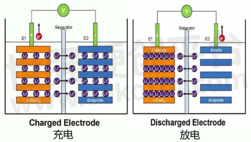
Reaction on the charging positive electrode: LiCoO2=Li(1-x)CoO2+xLi++xe-(electron)
Reaction on the charging negative electrode: 6C+xLi++xe-= LixC6
Rechargeable battery total reaction: LiCoO2+6C=Li(1-x)CoO2+LixC6
Positive electrode
Positive electrode material: There are many optional positive electrode materials, and the common positive electrode active materials in the market are shown in Table 1.

Table 1
Positive electrode reaction: Li-ion intercalation during discharge and de-intercalation of Li-ion during charging, as shown in Figure 1.

When charging: LiFePO4=Li(1-x)FePO4+xLi++xe-
During discharge: Li(1-x)FePO4+xLi++xe-=LiFePO4
negative electrode
Negative electrode material: Graphite is mostly used. In addition, lithium metal, lithium alloy, silicon carbon anode, oxide anode material, etc. can also be used for the anode.
Negative reaction: lithium ions are deintercalated during discharge, and lithium ions are embedded during charging.
When charging: xLi++xe-+6C=LixC6
When discharging: LixC6=xLi++xe-+6C
Lithium battery charging management
The widespread use of lithium batteries has increased the demand for battery capacity of some products, and it is necessary to connect multiple lithium batteries in series, which will lead to an increase in the total voltage of the battery, so Aichuang Micro has spawned lithium battery charge management chip products.
AICHUANGWEI's lithium battery charging management chip can effectively manage the charging of each lithium battery. It will automatically perform precharge, constant current charging, and constant voltage charging according to the characteristics of the lithium battery. For lithium batteries, the battery management chip manages various performance management of battery charging and discharging, such as constant voltage mode, constant current mode, etc. These charging methods are beneficial to the battery, and the most important point is that relatively speaking, it will be more Safety.
In addition, the lithium battery management chip has a significant effect on the battery life extension, because there is a charge and discharge chip. The voltage and current have reached a controllable state, which can effectively control the charging state of each stage of charging. The management chip is a circuit designed to protect the battery, which can protect the battery from over-discharge, over-voltage, over-charge, and over-temperature, and can effectively protect the battery life and user safety.
Aichuangwei's lithium battery charging management chip has the characteristics of full function, low price, high integration, simple external circuit, convenient adjustment and good reliability. Therefore, it is an important choice to be equipped with a management chip when charging the lithium battery. Next, I will recommend a lithium battery charge management chip ICW5012-N product.
Lithium battery charge management IC
ICW5012-N is a single-cell lithium-ion battery constant voltage and constant current charging management chip with a withstand voltage of 9V from Hefei Aichuang Microelectronics Technology Co., Ltd. The maximum charging current can reach 1.3A. In poor cases, it will generate serious heat. There is a thermal feedback circuit inside to control the temperature of the chip during the charging process and adjust the charging current to a lower level to meet the corresponding system heat dissipation requirements. Available in an SOP8 package with thermal PAD, plus few external components, making it ideal for portable applications.
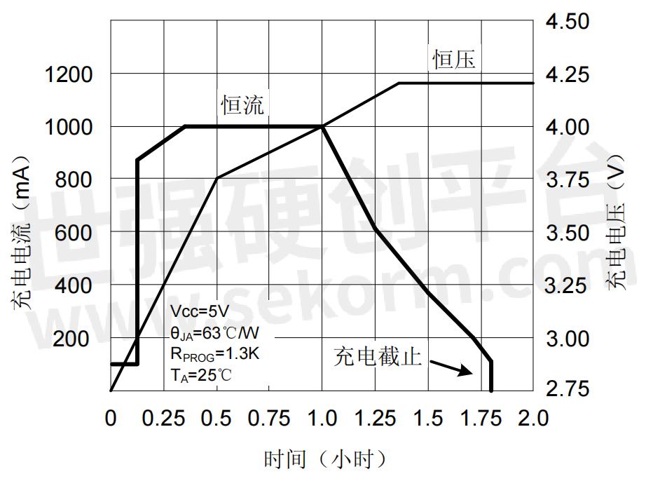
The ICW5012-N does not require a current sense resistor, nor does it require an external blocking diode for anti-backflow applications. The charging cut-off voltage is fixed at 4.2V14.34V14.4V, and the charging current can be adjusted by an external resistor. When the charging current reaches 1/10 of the constant current current, the ICW5012-N will terminate the charging. A typical application charge cycle is shown in Figure 2.

figure 2
When the input voltage (adapter or USB) is taken, the ICW5012-N enters sleep mode. The charging path is automatically turned off inside the chip, and the input voltage becomes lower. At this time, the battery leakage current is reduced to below 2μA. When the ICW5012-N is powered and the battery is removed, the chip current is reduced to 55μA to reduce system losses.
The ICW5012-N also features battery temperature detection, input undervoltage lockout, automatic recharge and two charge indication pins.
The working principle of ICW5012-N
ICW5012-N is a single-cell lithium battery charging management chip with constant voltage and constant current charging characteristics. The maximum charging current can reach 1.3A, and no additional diodes and current-sense resistors are required. The ICW5012-N includes two status indication terminals of open-drain output: charging status indication CHRG and battery failure status indication output terminal STDBY.
The thermal feedback circuit inside the chip will automatically reduce the charging current when the temperature exceeds 145°C. This feature allows the user to maximize the power handling capability of the chip. There is no need to worry about the chip overheating and damage to the chip or external devices, which ensures the reliability of the chip to the greatest extent.
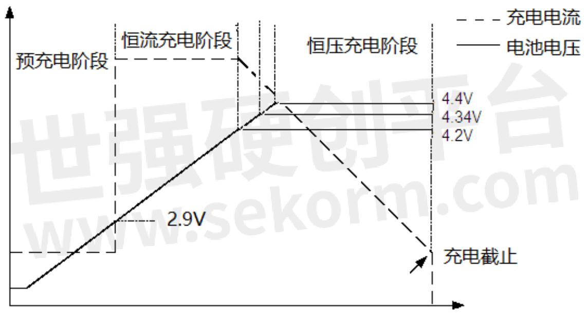
When the input voltage is greater than the under-voltage protection threshold and the enable terminal is connected to a high level, the ICW5012-N starts to charge the battery, and the CHRG pin outputs a low level, indicating that charging is in progress. If the battery voltage is lower than 2.9V, the charger uses A small current precharges the battery. When the battery voltage exceeds 2.9V, it switches to constant current mode to charge the battery, and the charging current is determined by the resistance between the PROG pin and GND. As the battery voltage approaches 4.2V (or 4.34V or 4.4V), the charging current gradually decreases. When the current decreases to the charging end threshold (1/10 of the constant current), the charging cycle ends, the CHRG terminal outputs a high-impedance state, and STDBY outputs a low potential.

When the battery voltage falls below the recharge threshold, a new charge cycle begins automatically. The high-precision voltage reference source, error amplifier, and resistor divider network inside the chip ensure that the modulation voltage accuracy at the battery terminal is within 1%. Meet the requirements of Li-ion and Li-polymer batteries. When the input voltage is powered down or the input voltage is lower than the battery voltage, the charger enters sleep mode. Battery-side leakage current is as low as 2μA, increasing standby time. If the enable terminal is tied low, the chip will stop charging. The charging process is shown in Figure 3.
Finally, to popularize some of the following ten reasons for the explosion of lithium batteries, you can also take corresponding preventive measures in peacetime.
1. The internal polarization is large;
2. The pole piece absorbs water and reacts with the electrolyte;
3. The quality and performance of the electrolyte itself;
4. When injecting liquid, the amount of liquid injection cannot meet the process requirements;
5. The laser welding sealing performance is poor in the assembly process, and the air leaks when the air leak is detected;
6. Dust and pole piece dust is easy to cause micro-short circuits first;
7. The positive and negative plates are thicker than the process range, and it is difficult to enter the shell;
8. The problem of liquid injection and sealing, the poor sealing performance of steel balls leads to air bulging;
9. The incoming shell material has a thick shell wall, and the shell deformation affects the thickness;
10. The high ambient temperature outside is also the main reason for the explosion.
- +1 Like
- Add to Favorites
Recommend
- How to Prevent Electrostatic Discharge in EMC Circuit Design?
- Principle and Application of Linear Regulator LDO
- What Is LED Driver Power Supply?
- How is the Lithium Battery Charged?
- Bike Light Battery Solution - Grepow GRP8024037 3.7V 600mAh Lithium Battery
- Omnergy Brand Blister Package Lithium Battery- Compact Lithium Battery with Strong Battery Core, Intelligent Application of “strong Core“ Design
- Is the Button Battery a Lithium Battery or a Dry Battery?
- What‘s The Cycling And Float Of a Lithium Battery?
This document is provided by Sekorm Platform for VIP exclusive service. The copyright is owned by Sekorm. Without authorization, any medias, websites or individual are not allowed to reprint. When authorizing the reprint, the link of www.sekorm.com must be indicated.


