Epson Expands Its Lineup of 1-inch Platform IMUs with a Low-Noise Premium Model M-G370PDT

Seiko EPSON Corporation (TSE: 6724, "Epson") has expanded its lineup of inertial measurement units1 (IMU) equipped with high-performance, six degrees of freedom sensors. The new M-G370PDT ("M-G370T" below) is a low-noise premium model that is now in volume production and began shipping in February 2024.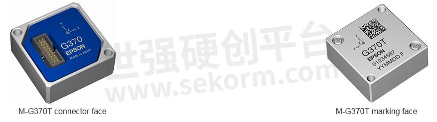
First launched in 2011, Epson's IMUs have been used in an array of customer applications, from precision agriculture (GNSS2), low earth orbit small satellites3 using consumer industrial components, and EO/IR camera gimbals4 to antenna platform vibration control and stabilization, earning an excellent reputation for outstanding performance and quality. In recent years, IMU use has expanded into fields such as aerial surveying and low earth orbit satellite video photography, creating a growing need for more accurate position and attitude control. Accordingly, demand is rising for IMUs that offer greater precision, which is crucial in attitude control, and especially noise performance.
The M-G370T is a one-inch model that combines the best features of two current models, the M-G370PDS and the M-G370PDG, and offers both low noise and high accuracy measurement. It has the same 0.03°/ √h angle random walk5 (an important IMU performance indicator for short-term variation in output) as the M-G370PDS ("M-G370S" below) and also has high noise immunity to more accurately detect slight attitude changes that occur in equipment and systems. Also, like the M-G370PDG ("M-G370G" below), the new IMU allows users to select an accelerometer output range of either ±8G or ±16G. It also offers 0.05% non-linearity6 on the full-scale range of the gyroscopic sensor.7 These features enable the new IMU to accurately measure all types of motion, from slow to fast.
By expanding and enhancing its lineup of one-inch platform products, Epson is giving customers more options, allowing them to choose a product that has the best functions and performance for their particular needs and applications.
Given the social and technological changes that are underway, Epson believes that the need for precision sensors will only expand going forward. We will continue to leverage our philosophy of efficient, compact, and precise innovation to provide small, lightweight, low-power sensing systems that offer outstanding precision, high stability, and low noise to significantly contribute to our customers' products and services.
Product Features
One-inch platform (24 x 24 x 10 mm³)
Cross compatible with M-G370S and M-G370G, sharply reducing customer development costs and evaluation timeAngle random walk of 0.03°/√h
User selectable accelerometer output range at ±8G or ±16G
Gyroscopic sensor non-linearity is 0.05% for the sensor's full scale range
Low current consumption: 16 mA
Product Applications
Stabilization control for low earth orbit small satellites using consumer industrial components, EO/IR camera gimbals, antennas, etc.
Unmanned vehicles (industrial drones, terrestrial vehicles, sea probes, etc.)
Vibration, angle, trajectory measurement of industrial equipment, etc.
Navigation systems (GNSS, INS8, high-precision locators), etc.
General Specifications of the M-G370T and 1-Inch Platform Products

Note: The specified values are typical values unless stated otherwise.
1 Inertial measurement unit (IMU)
An IMU is a device that is used for sensing inertial motion. It is comprised of triaxial angular rate sensors and triaxial accelerometers.
2 A global navigation satellite system (GNSS)
A satellite system that is used to pinpoint a geographic location anywhere in the world
3 This product and other Epson IMUs do not conform to the standards for use in space.
4 EO/IR camera gimbal
An electro-optical, infrared camera system
5 Angle random walk
The part of the Allan variance with a slope of -1/2 is called the angle random walk. Since there is a correlation with white noise, increasing the average time decreases the value at -1/2 of the average time.
6 Non-linearity
The maximum deviation from an approximate straight line of the output versus input of a gyroscopic sensor or accelerometer. It is typically expressed as a percentage of the full scale.
7 Gyroscopic sensor (angular rate sensor)
Measures the rotation angle (angular rate) of an object versus a reference axis per unit of time
8 INS
Inertial navigation system
9 Bias instability
The part of the Allan variance* that represents the horizontal (zero power) characteristic is called bias instability. It correlates with 1/f noise and is one of the important indicators of sensor potential.
* Allan variance
An indicator of sensor performance, the Allan variance indicates the stability of the static output. The horizontal axis shows the averaging time of data, and the vertical axis shows the distribution of the average value when separated by the average time.
It is known that the slopes of the characteristics appearing in the Allan variance are -1, -1/2, 0, 1/2, and 1st power slopes, the Allan variance correlates with the noise density, and the noise density is the frequency. Allan variance is an indicator expressed in time.
The smaller the value, the higher the stability and the better the performance.
- +1 Like
- Add to Favorites
Recommend
- Epson Expands Its Lineup of One-Inch Platform IMUs with High-Spec M-G370PDG Entering Volume Production in July 2023
- News | Epson Launches 4th-Generation Optical Engine for Smart Glasses
- Epson IMU Adopted by JAXA for “Int-Ball2“ Free-flying Camera Robot Used on ISS Japanese Experiment Module
- Epson Develops the Ideal IMU for Attitude and Vibration Control
- Epson Expands Its Lineup of G-series IMUs with the Development of M-G366PDG and M-G330PDG
- A Key Technology in Precision Agriculture: Epson‘s IMU Combined with GNSS Can Accurately Measure Objects as It Moves in Three-dimensional Space
- Epson‘s High-performance Cushioning Material Wins the WorldStar Global Packaging Awards 2024 in the Electronics Category
- Seismic Intensity Meters Equipped with Epson‘s M-A352 Accelerometer Certified by the Japan Meteorological Agency
This document is provided by Sekorm Platform for VIP exclusive service. The copyright is owned by Sekorm. Without authorization, any medias, websites or individual are not allowed to reprint. When authorizing the reprint, the link of www.sekorm.com must be indicated.
Integrated Circuits


Discrete Components


Connectors & Structural Components


Assembly UnitModules & Accessories


Power Supplies & Power Modules


Electronic Materials


Instrumentation & Test Kit


Electrical Tools & Materials


Mechatronics


Processing & Customization


