Epson Expands Its Lineup of G-series IMUs with the Development of M-G366PDG and M-G330PDG

Seiko EPSON Corporation (Epson) has expanded its lineup of inertial measurement units (IMU)1 equipped with high-performance six-axis sensors by adding a newly developed standard model called the M-G366PDG ("M-G366") and a basic model called the M-G330PDG ("M-G330"). Samples will begin shipping in January 2023. Volume production is scheduled to start in the spring of 2023.
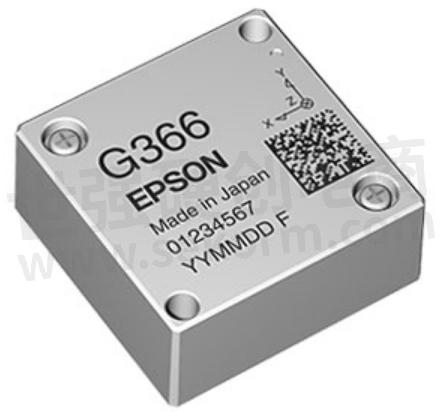
M-G366PDG

M-G330PDG
First launched in 2011, Epson's IMUs have been used in an array of customer applications, from precision agriculture (GNSS2) and drones to camera and antenna platform vibration control and stabilization, earning an excellent reputation for outstanding performance and quality. Epson's lineup of IMUs includes the high-spec M-G370PDS ("M-G370S") and M-G370PDF ("M-G370"), which provide high stability and high-precision measurement capability along with low noise and are one-inch platforms that measure approximately one-inch along the sides. To expand the options at this size, Epson added the M-G366 as a standard model and the M-G330 as a basic model.
The M-G366 and M-G330 allow users to select an accelerometer output range of either ±8G or ±16G. In addition, they offer 0.05% non-linearity3 in all output ranges of the gyroscopic sensors, making it possible to accurately measure various movements, whether slow or fast. By expanding its lineup of small, lightweight, low-power, one-inch platform products, Epson will enable customers to choose a product with the best functions and performance for their application.
The M-G366 and M-G330 will be exhibited at Maintenance & Resilience Osaka 2022, an event organized by the Japan Management Association that is to be held from December 7 to 9 at INTEX Osaka. In addition, Epson will exhibit these products at the 2nd Nepcon Japan Online, a virtual event organized by RX Japan Ltd., from November 30 to December 2.
Given the social and technological changes that are underway, Epson believes that the need for precision sensors that can visualize information will only expand going forward. Epson will continue to leverage its philosophy of efficient, compact, and precise innovation to provide small, lightweight, low-power sensing systems that offer outstanding precision and stability to significantly contribute to our customers' products and services.
Product Features
One-inch platform (24x24x10mm³)
Downward compatible with the M-G370 and M-G370S, sharply reducing customer development costs and evaluation time
The accelerometer output range is user selectable at ±8G or ±16G
0.05% gyroscopic sensor non-linearity
Low current consumption: 16mA
Product Applications
Unmanned vehicles (industrial drones, terrestrial vehicles, sea probes, etc.)
Vibration damping for cameras, antennas, etc.
Vibration, angle, trajectory measurement of industrial equipment, etc.
Navigation systems (GNSS, INS4, high-precision locators), etc.
General Specifications
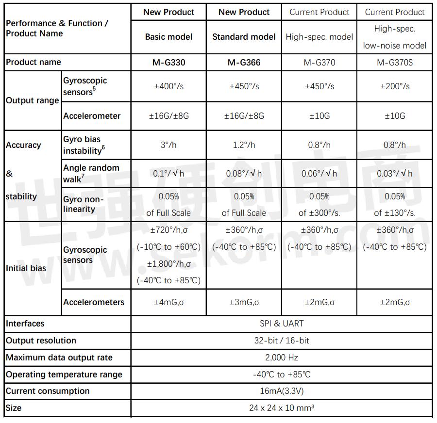
Note: The specified values are typical values unless stated otherwise.
1 Inertial measurement unit (IMU)
An IMU is a device that is used for sensing inertial motion. It is comprised of triaxial angular rate sensors and triaxial accelerometers.
2 A global navigation satellite system (GNSS)
A satellite system that is used to pinpoint a geographic location anywhere in the world
3 Non-linearity
The maximum deviation from an approximately straight line of the output versus input of a gyroscopic sensor or accelerometer. It is typically expressed as a percentage of the full scale.
4 Inertial navigation system (INS)
5 Gyroscopic sensor (angular rate sensor)
Measures the rotation angle (angular rate) of an object versus a reference axis per unit of time.
6 Bias instability
The part of the Allan variance* that represents the horizontal (zero power) characteristic is called bias instability. It correlates with 1/f noise and is one of the important indicators of sensor potential.
7 Angle random walk
The part of the Allan variance with a slope of -1/2 is called the angle random walk. Since there is a correlation with white noise, increasing the average time decreases the value at -1/2 of the average time.
* Allan variance
An indicator of sensor performance, the Allan variance indicates the stability of the static output. The horizontal axis shows the averaging time of data, and the vertical axis shows the distribution of the average value when separated by the average time. It is known that the slopes of the characteristics appearing in the Allan variance are -1, -1/2, 0, 1/2, and 1st power slopes, the Allan variance correlates with the noise density, and the noise density is the frequency. Allan variance is an indicator expressed in time. The smaller the value, the higher the stability and the better the performance.
- 【Datasheet】M-G32EV041 USB Evaluation Cable Interface Board for EPSON IMU/Accelerometer
- 【Datasheet】M-G32EV051 Relay board for EPSON Accelerometer/IMU
- +1 Like
- Add to Favorites
Recommend
- News | Epson Launches 4th-Generation Optical Engine for Smart Glasses
- Epson‘s High-performance Cushioning Material Wins the WorldStar Global Packaging Awards 2024 in the Electronics Category
- Seismic Intensity Meters Equipped with Epson‘s M-A352 Accelerometer Certified by the Japan Meteorological Agency
- Epson Develops an New Industrial 3D Printer that Can Use Commonly Available Materials
- High-stability GYRO Sensor by Epson with Bias Output Stability and Low Noise
- Epson Becomes the Manufacturing Industry‘s First to Switch to 100% Renewable Electricity at All Sites in Japan
- Epson to Start Selling New Sensing Technologies and Launch New Sensing Analysis Technology Business
- Epson Shipping Samples Of Low-Power 16-Bit Microcontrollers Equipped with High-Precision A/D Converter
This document is provided by Sekorm Platform for VIP exclusive service. The copyright is owned by Sekorm. Without authorization, any medias, websites or individual are not allowed to reprint. When authorizing the reprint, the link of www.sekorm.com must be indicated.
Integrated Circuits


Discrete Components


Connectors & Structural Components


Assembly UnitModules & Accessories


Power Supplies & Power Modules


Electronic Materials


Instrumentation & Test Kit


Electrical Tools & Materials


Mechatronics


Processing & Customization


