PEPS (Passive Entry And Startup) System Circuit Protection Solution

After two generations of products, the car's entry system has evolved from the blade mechanical key and the traditional wireless key key (RKE) to the PE (Passive Entry) mode that can be entered without pressing a button; at the same time, the starting and ignition of the car engine have also After experiencing changes in mechanical cranks, motor ignition, password keys, etc., we have come to the PS (Passive Start) mode of keyless start.
PEPS Structural Composition And Basic Functions
The PEPS system generally includes two parts: a vehicle base station (PEPS controller + body controller BCM) and a wireless tag (PEPS smart key).

Fig.1
Vehicle Base Station >>PEPS Controller
The PEPS controller is the core component of the PEPS system and mainly includes the following functional modules:
1. Door handle and trunk switch detection module
Check whether the door handle or trunk switch is touched.
2. Low-frequency LF antenna driver module
Drives 125kHz low-frequency antenna; there are generally 6~8 low-frequency antennas arranged in the car, and the arrangement is as shown in Figure 1. Drives low-frequency antennas and transmits effective signals to wake up the key and send the encrypted data to the key.
3.Radiofrequency RF data receiving module
Responsible for receiving the high-frequency signal transmitted by the smart key, analyzing the key position, verifying the legality of the key, and providing door unlocking and start unlocking control instructions based on whether the key matches.
4. Supply module for electronic steering column lock
Provides power to the electronic steering column lock. The electronic steering column lock is only required when the electronic steering column lock needs to be unlocked and diagnosed. At other times, it will not be powered.
5. Electronic steering column lock ESCL control module
Communicate with the electronic steering column lock through LIN bus communication to complete unlocking control and diagnosis operations. Cooperating with the IMMO anti-theft module, the steering column (steering wheel) is locked before unlocking. Even if you forcefully enter the car, you will not be able to start driving.
6. Power PDU Distribution Relay Driver Module
Responsible for controlling the relay group and finally completing the function of switching power supply gears.
7. Start button status indication module
According to the gear position and starting conditions, the LED indicator light on the button is driven. According to the LED light indication, for example, after the vehicle self-inspection is completed, the light turns green, and the driver can press the button to start the engine.
8. Diagnostic and alarm module
Responsible for communicating with the instrument in the form of the CAN bus, realizing alarm and prompt functions, and realizing diagnostic functions through the CAN bus.
9.Anti-theft system IMMO certification module
It is responsible for completing related anti-theft authentication functions.
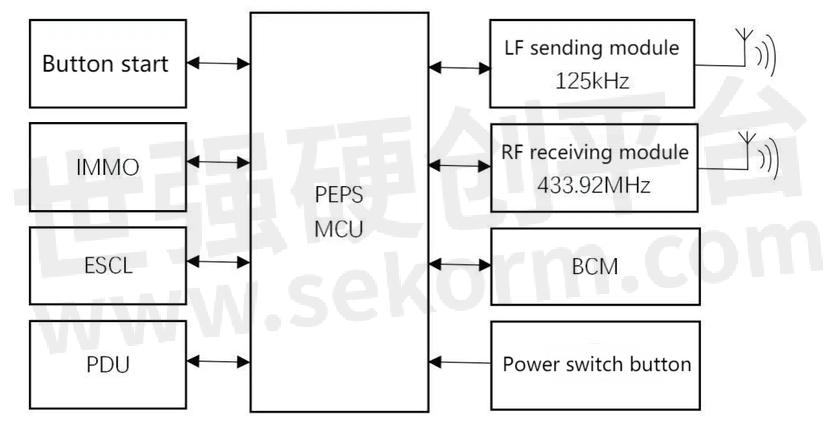
Fig.2
Positioning Tag >> PEPS Smart Key
The main modules and functions of the PEPS smart key are:
1. Conventional remote control key (RKE) system
The smart key is compatible with the functions of traditional RKE and retains some buttons, which is in line with the original habit of using buttons to unlock, open the trunk, lock, etc.; such as remote unlocking and remote lifting windows.
2. Low-frequency LF receiving module
Receive the low-frequency LF signal (125kHz) from the vehicle-mounted PEPS base station, wake up the key circuit system, and exit the sleep power-saving mode;
3. Radiofrequency RF transmitting module
Send relevant information to the vehicle-mounted PEPS system, match the key, and obtain entry or button start authorization.
4. Sound and light instructions
Some smart keys retain an LED or buzzer, and use sounds or lights to prompt alarms or indicate car information.
5. Other module circuits
Such as the main control chip, etc.
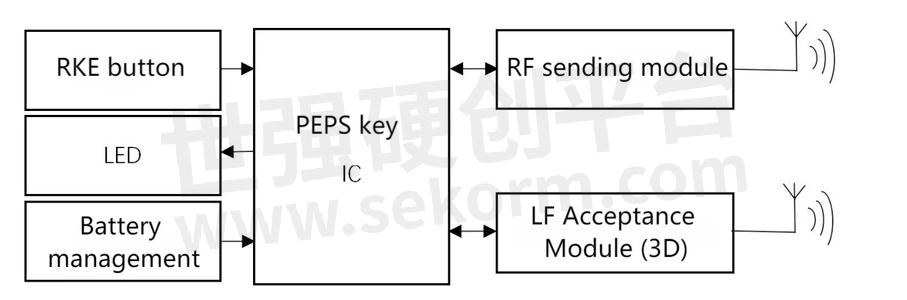
Fig.3
- +1 Like
- Add to Favorites
Recommend
- A 12V DC Lightning Protection Solution from Yint
- Yint Electronics Recommends Using a Varistor for Input Overvoltage Protection of Smart Meters
- Yint Electronics Provides Effective Circuit Protection for UWB Positioning Base Stations
- Yint Electronics MOV 14D561K, TVS SMBJ6.5CA P6SMBJ10CA for Power Line Carrier PLC Interface Circuit
- How To View The Importance Of Power Surges To The System?
- The Rise in Copper Prices And Its Impact on Electronic Component Costs
- The Applications of PPTC Protection Devices in Wireless Electronic Products, Battery Packs, Chargers, Power Converters and Transformers
- Yint Electronics provides the SD/TF Memory Card Interface Solution
This document is provided by Sekorm Platform for VIP exclusive service. The copyright is owned by Sekorm. Without authorization, any medias, websites or individual are not allowed to reprint. When authorizing the reprint, the link of www.sekorm.com must be indicated.
Integrated Circuits


Discrete Components


Connectors & Structural Components


Assembly UnitModules & Accessories


Power Supplies & Power Modules


Electronic Materials


Instrumentation & Test Kit


Electrical Tools & Materials


Mechatronics


Processing & Customization


