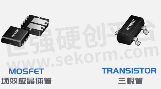
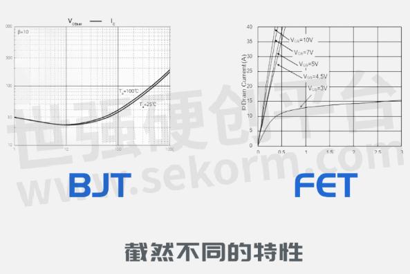
The Difference between Transistor and Field-effect Transistor

1. Structure:
Triode: A transistor consists of two PN structures, with a central P-type or N-type region called the base region and two peripheral P-type or N-type regions called the emission region and collector region.
Field effect transistor: A field effect transistor is composed of three main regions, namely gate, drain, and source. There is an insulation layer between the gate and drain called the gate oxide layer.

2. Control signal:
Triode: The collecting current of a transistor is controlled by the base current. When the base current flows in, it controls the current flow in the emitter-collector region.
Field effect transistor: The drain current of a field effect transistor is controlled by the gate voltage. When the gate voltage changes, it affects the current flow between the drain and source electrodes.
3. Polarity:
Triode: There are two types of transistors, NPN type and PNP type, which are composed of N-type and P-type materials, respectively. In NPN-type transistors, the base region is P-type, while the N-type is the emission region and collector region. In a PNP-type transistor, the base region is N-type, while the P-type is the emission region and collector region.
Field effect transistor: There are also two types of field effect transistors, N-Channel and P-Channel, which are composed of N-type and P-type materials, respectively.
4. Working mode:
Triode: The transistor can be operated in two operating modes, namely amplification mode and switching mode. In amplification mode, the transistor is used as a current amplifier, while in switching mode, it is used as a switch for the circuit.
Field effect transistor: Field effect transistor can operate in two operating modes, namely enhancement and depletion. Enhanced field-effect transistors require a forward bias voltage to conduct, while depleted field-effect transistors require a negative bias voltage to conduct.
5. Frequency response
Triode: The frequency response of a transistor is relatively low, usually within the range of tens of MHz.
Field effect transistor: The field effect transistor has a relatively high-frequency response, which can reach frequencies of several hundred MHz or higher.
The choice of which device to use mainly depends on specific application requirements and circuit design requirements. Below are some differences in their application aspects:
1. Enlarge the application:
Triode: Due to its high current amplification ability and low input resistance, it is usually used in amplifier circuits that require high gain. It is widely used in applications such as audio amplifiers, RF amplifiers, and power amplifiers.
Field effect transistor: Due to its high input resistance and high-frequency response, field effect transistors are typically used in amplifier circuits with high impedance inputs. It is common in low-noise amplifiers, high-frequency amplifiers, and RF applications.
2. Switch application:
Transistor: Due to its low output resistance and high switching speed, it is suitable for relatively high current and high power switching applications. It is commonly used in switching power supplies, drive motors, and switching circuits.
Field effect transistor: Field effect transistors have high input resistance and low power consumption, making them suitable for relatively low current and low power switching applications. It is commonly used in fields such as analog switches, digital logic gates, CMOS circuits, and power management.
3. High frequency applications:
Transistor: Due to its limited frequency response, its use in high-frequency applications is limited. It performs well in the mid to low-frequency range but has few applications in the RF and microwave fields.
Field effect transistor: Due to its high-frequency response and low input and output resistance, field effect transistor performs well in RF and high-frequency applications. It is widely used in fields such as wireless communication, radar, high-speed digital circuits, etc.

The main reasons why field-effect transistors (FETs) are gradually replacing transistors (BJTs) in many applications are as follows:
1. High input impedance:
FET has a very high input impedance, which means it has little impact on the load of the input signal and will not cause significant distortion to the input signal. This makes FETs more suitable for use in many sensors, amplifiers, and high-impedance input circuits, especially in applications that require processing weak signals or low power.
2. Low power consumption:
FET has lower power consumption characteristics compared to BJT. The working principle of FET does not require a base current, only an electric field is applied to control the drain current. This leads to lower power consumption and higher efficiency of FETs in switching and amplification applications. In mobile devices, battery powered devices, and low-power applications, FETs can extend battery life and reduce system energy consumption.
3. High frequency response:
FET has a better frequency response and can operate in a higher frequency range. Due to its smaller input and output capacitance, as well as shorter carrier transmission paths, FETs perform better in RF and high-speed digital applications. This makes FET the preferred device in fields such as wireless communication, high-speed data transmission, and radar systems.
4. Integration and manufacturing process:
FET is easier to integrate into microelectronic chips compared to BJT, especially in modern CMOS (complementary metal oxide semiconductor) processes. CMOS technology is widely used in the manufacturing of integrated circuits, and the characteristics of FETs and other circuit components can be implemented on the same chip. This improvement in integration can lead to higher reliability, lower costs, and more compact designs.
Overall, there are significant differences between transistors and field-effect transistors in terms of structure, control signal, polarity, input resistance, operating mode, and frequency response. The choice of which device to use mainly depends on the specific application requirements and circuit design requirements. Although field-effect transistors have shown advantages in many aspects, transistors still have their advantages in some specific applications. For example, transistors have high current amplification capability and low output resistance, making them suitable for applications that require higher power and lower voltage. Therefore, in specific application scenarios, there is still a demand for the application of transistors.
- +1 Like
- Add to Favorites
Recommend
- How Does The Field Effect Transistor Work?
- Hybrid MOS transistor AO8804 Can be Used in Switch Circuit and LED Driving Circuit
- CHK8013-99F,a GaN Wideband Capability Transistor Covering DC to 10GHz from UMS
- PNP Transistor TIP32A Can be Used in Audio Amplifier, Motor Driver and Power Supply
- UMS Newly Launched CHK8201-SYA Transistor with Covering DC to 4GHz and A Linear Gain of 22dB
- Stylish LED Lights Arrays Controlled by Diotec’s Dual Transistor BC846S
- Characteristics and Application Scenarios of High Voltage MOS Transistor
- P-channel MOS transistor SI2301 can be Used for LED and Motor Driving Applications
This document is provided by Sekorm Platform for VIP exclusive service. The copyright is owned by Sekorm. Without authorization, any medias, websites or individual are not allowed to reprint. When authorizing the reprint, the link of www.sekorm.com must be indicated.


