Yint Developed CBR- series PPTC Thermistors which can Solve the Problem of Abnormal State Protection of Electronic Ballasts

As a recognized green lighting product, electronic ballast fluorescent lamps have many obvious advantages over ordinary inductive ballast fluorescent lamps, such as high luminous efficiency, no flicker, and significant energy-saving effects; however, some electronic ballasts also have higher failure rates. Disadvantages: For end customers, electronic ballasts have become high-cost (relative to inductive ballasts) disposable products.
Through our research, we found that one of the main reasons for the above problems is that some electronic ballast manufacturers did not take reliable protection measures against the abnormal status of the electronic ballast due to various reasons, thus causing the electronic ballast to follow the lamp. scrapped at the end of its life.
The general electronic ballast design scheme and related basic principles are as shown in the figure below

Fig.1
Under normal circumstances, after the electronic ballast is powered on, the inverter, together with the inductor L, filament 1, capacitor, and filament 2, form a series resonant circuit. High voltage is generated at both ends of the capacitor within a certain period of time. This high voltage causes the arc discharge of the fluorescent lamp to start the fluorescent lamp, and then the resonant circuit is detuned and the fluorescent lamp enters a stable ignition state.
When abnormal conditions such as lamp aging or lamp leakage occur, the fluorescent lamp cannot start normally, and the above circuit is always in a resonant state (unless the filament is burned out or the electronic ballast is damaged), and the current output by the inverter continues to increase. Usually, this current will increase to 3 to 5 times the normal current. If effective protective measures are not taken at this time, great harm will be caused. First of all, excessive current will cause the triode or field effect transistor and other peripheral components used as switches in the inverter to burn out due to overload, and even cause accidents such as smoke and explosion. At the same time, the lamp pin will form an extremely high voltage for a long time to the ground or neutral line. For electronic ballasts of 20W, 36W, 40W, and most other national standard/non-standard lamps, this voltage will often reach one thousand volts or more. High, this is not only strictly prohibited by the national standard GB15143 but also endangers personal and property safety.
Electronic Ballast Abnormal State Protection Scheme:
At present, electronic ballasts use more protection measures, including the following:
1. Connect a glass tube fuse in series to the AC input circuit. Connecting a fuse in series at this position may cause some people to mistakenly think that it will play a role in overcurrent or overload protection; in fact, such a protection method generally does not provide protection under overload conditions such as filament deactivation. It is often used in switching devices. It will fuse only after a breakdown, and it cannot play a real protective role in abnormal conditions.
2. Use a protection circuit with a thyristor, bipolar transistor, or field effect transistor as the core of the rectifier output circuit. The biggest advantage of this electronic circuit protection method is that the protection time is short, but it also has the following disadvantages:
(1) False protection is prone to occur: If for some reason, even a very short sharp pulse is formed at the trigger end of the thyristor, it will cause the inverter to stop working, causing the light to go out.
(2) The design and debugging work is relatively cumbersome: Under normal circumstances, this kind of protection circuit will have at least 6 electronic components including resistors, capacitors, and pulse transformer secondary coils. At the same time, many components are used together with active components such as thyristors. Problems such as device discreteness and temperature drift will increase the difficulty of debugging, thereby affecting production efficiency.
(3)this protection method also has the disadvantages of higher cost and larger PCB space occupation, which is also a headache for many electronic ballast manufacturers.
3. Connect a self-restoring polymer PTC thermistor in series next to the resonant circuit, that is, the resonant capacitor. Figure 2 is a schematic diagram of a circuit using a Polymer PTC Thermistor to protect electronic ballasts from abnormalities.
When the lamp is normal and the electronic ballast is powered on, the resonant circuit composed of the inductor, capacitor, and PTC thermistor causes the fluorescent lamp to start working normally. If the lamp is deactivated due to filament aging or air leakage, the PTC thermistor will act within a few seconds, forcing the LC series resonant circuit to stop vibrating, thus cutting off the high voltage and protecting the switching devices in the inverter.

Fig.2
The advantages of this protection method have been recognized by many electronic ballast manufacturers, but it has not been widely used so far. The main reason is that the PTC components currently provided on the market cannot meet the particularities of electronic ballast use. , the main problems currently are:
(1) It is easy to malfunction due to high temperature or the operation time is too long when deactivated;
(2)When the PTC thermistor is in the protection state for a long time (for example, 24 hours), it is prone to irreversible increase in resistance and serious performance degradation. This is the main reason why most polymer PTC thermistors have not been successfully used in electronic ballasts.
In response to the above problems, Shanghai YINT Electronics Co., Ltd. has developed the CBR- series of PPTC thermistors specially used for electronic ballasts, which overcomes the above defects and can solve the problem of abnormal state protection of ballasts.
CBR
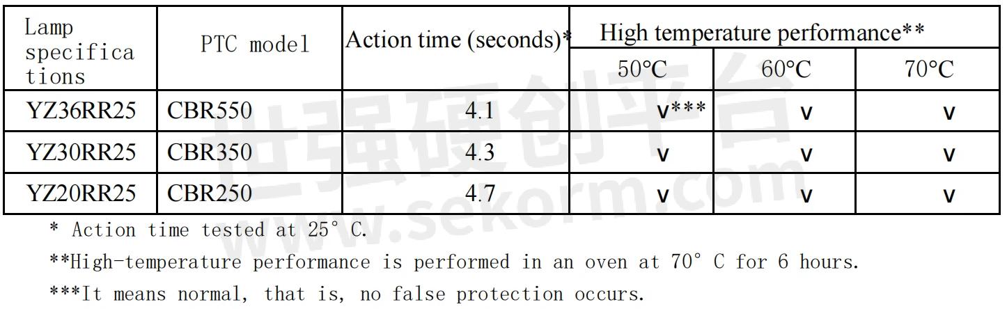
The single lamp protection test uses the circuit shown in Figure 1. The following are actual measured data of PTC in electronic ballast circuits.
1. Protection time and high-temperature performance.
Table.1
2. High temperature operating characteristics and protection time of the thermistor after multiple protections. Before this test, the PTC had been subjected to the following shocks: every 5 minutes and maintained in the deactivated state for 10 minutes; a total of 10 times. Test steps: First test the action time; then test the high-temperature performance. The test conditions are the same as 1.
Table.2

3. High temperature operating characteristics and protection time of the thermistor after long-term protection. The PTC used in this test has been deactivated by a fluorescent lamp and kept operating for 24 hours before conducting the following tests. The test steps are the same as 2.
Table.3

Through the above tests, we can conclude: that using a CBR thermistor, the fluorescent lamp can still work normally even in a high temperature environment of 70℃, and at the same time, good protection characteristics can be guaranteed at room temperature; on the other hand, PPTC maintains very stable performance even after providing protection multiple times or over long periods of time.
4. Application of CBR series PTC in double lamp electronic ballasts/multiple lamp electronic ballasts:
Usually, with electronic circuit protection methods such as thyristors, when one of the dual/multiple lamps is deactivated, it will cause the entire ballast to stop working, causing even normal fluorescent lamps to go out at the same time, which is often disturbing. of. The use of CBR series thermistors solves this problem. We can make an explanation through the following circuit.
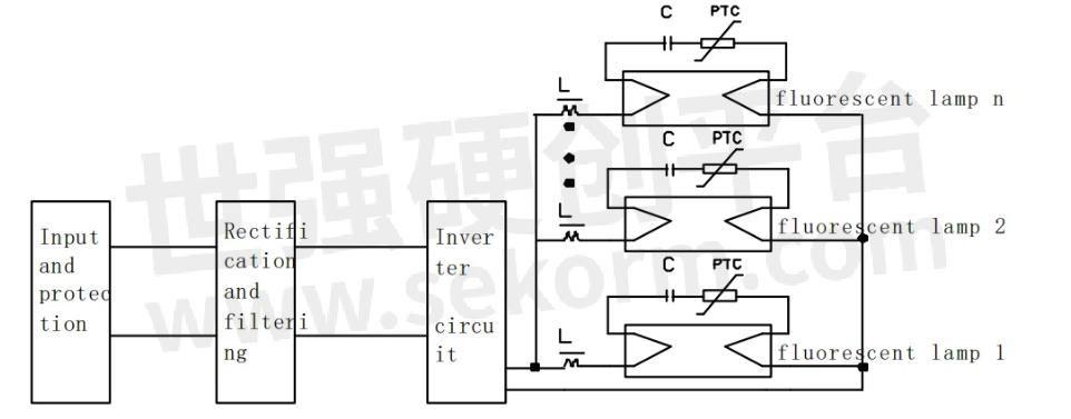
Fig.3
In the above figure, assuming that fluorescent lamp 1 is deactivated, PTC1 will act and the filament current of lamp 1 will be close to 0, but the operation of other fluorescent lamps will not be affected. In this way, users do not have to worry about which lamp has reached the end of its life or the ballast is damaged.
As can be seen from the above application examples, CBR series thermistors have the following obvious advantages:
(1) It is convenient for manufacturers to simplify circuit design, especially to provide simpler and more reliable protection for double lamps and multiple lamps.
design plan.
(2) Reduce the complexity of debugging and assembly, which will help improve production efficiency.
(3)It has good, comprehensive, and stable high and low-temperature performance.
(4) Reduce costs and save PCB space.
This series of resettable fuses can be applied to various national standard straight tube fluorescent lamps/non-standard straight tube fluorescent lamps, ring fluorescent lamps U-shaped lamps, etc.
- +1 Like
- Add to Favorites
Recommend
- A 12V DC Lightning Protection Solution from Yint
- Yint Electronics Recommends Using a Varistor for Input Overvoltage Protection of Smart Meters
- Yint Electronics Provides Effective Circuit Protection for UWB Positioning Base Stations
- Yint Electronics MOV 14D561K, TVS SMBJ6.5CA P6SMBJ10CA for Power Line Carrier PLC Interface Circuit
- How To View The Importance Of Power Surges To The System?
- The Rise in Copper Prices And Its Impact on Electronic Component Costs
- The Applications of PPTC Protection Devices in Wireless Electronic Products, Battery Packs, Chargers, Power Converters and Transformers
- Yint Electronics provides the SD/TF Memory Card Interface Solution
This document is provided by Sekorm Platform for VIP exclusive service. The copyright is owned by Sekorm. Without authorization, any medias, websites or individual are not allowed to reprint. When authorizing the reprint, the link of www.sekorm.com must be indicated.
Integrated Circuits


Discrete Components


Connectors & Structural Components


Assembly UnitModules & Accessories


Power Supplies & Power Modules


Electronic Materials


Instrumentation & Test Kit


Electrical Tools & Materials


Mechatronics


Processing & Customization


