RF-STAR Low Power Consumption BLE RF Modules RF-BM-ND05 Based on NRF52840 Chip

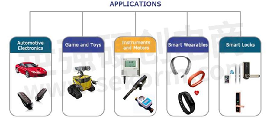
RF-Star RF-BM-ND05 are BLE RF modules.With advantages of low power consumption, compact design, long transmission distance and strong anti-interference capability, the modules embedded with high performance IFA, can be widely used in low power local area network communication.
RF-BM-ND05 built upon chip Nordic52840. The module can be used to develop consumer electronic products and phone peripherals over BLE 5.0. It provides a quick BLE solution for the communication between customer’s products to mobile devices.
Module Parameters
Pin assignment
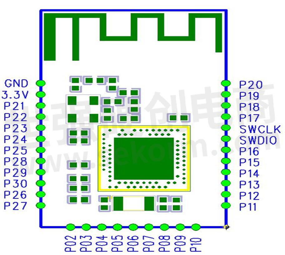
Figure 1 Pin assignment
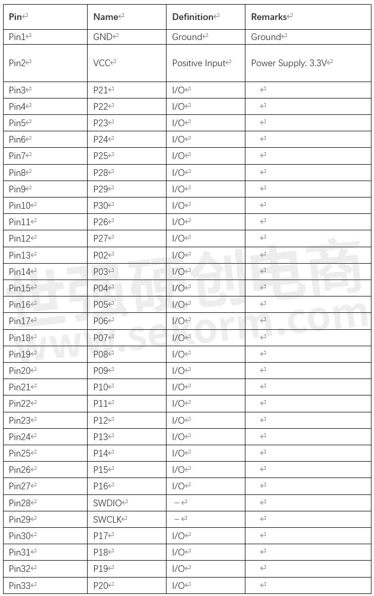
Package Size
Thickness of the module is 2.3 ± 0.1 mm。
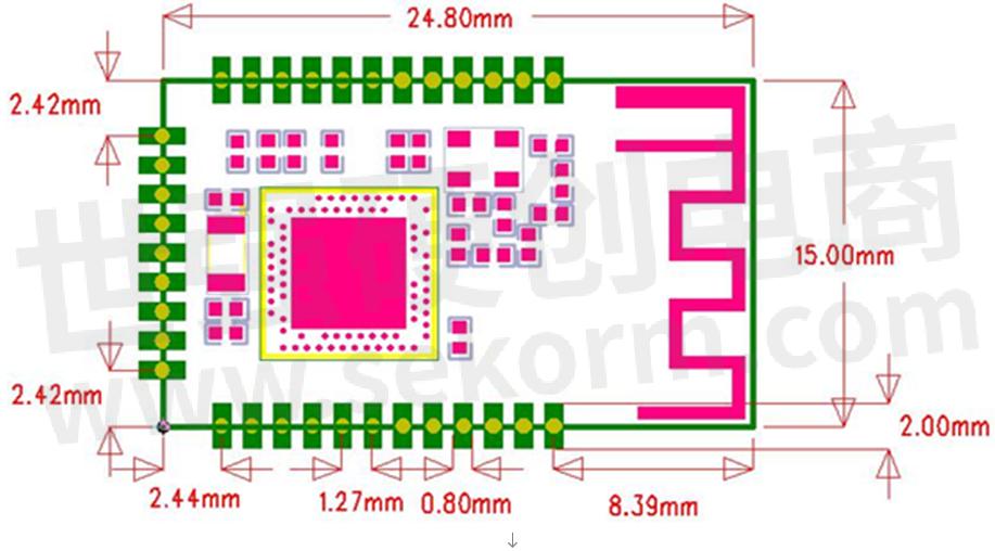
Figure 2 Package Size
Layout Proposals
The serpentine antenna on PCB is free space electromagnetic radiation. The place and layout range are keys to enhance the data rate and transmit range.
Thus,Below are the layout proposals for antenna and route:
1, Place the antenna on the edge(corner) of the PCB backplane.
2, Make sure there is no signal or copper foil in each layer.
3, Hollowing out the yellow pane part (figure 3) to make less S11 interference.
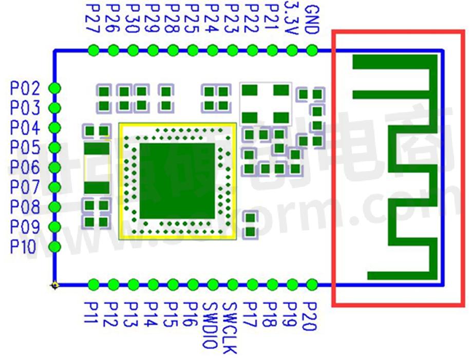
Figure 3
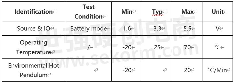
Recommended Operating Conditions
Notes:
(1) The operating temperature is limited to the change of crystal’s frequency.
(2) To ensure the RF performance, the ripple wave of the source must be less than 300mV.
Reflow Conditions
1. Heating mode:conventional convection or IR convection;
2. Times allowed to reflow: 2 times, for the below reflow (conditions)(figure 4);
3. Temperature curve: the reflow should be in accordance with the temperature curve shown below (figure 4);
4. Highest:245°C。
Figure 4 Parts’ heat-resistance temperature curve for welding(welding point)
Electrostatic Discharge
Module will be damaged for the discharge of static, RF star suggest that all modules should follow the 3 precautions below.:
1. According to the anti-static measures, bare hands are not allowed to touch modules.
2. Modules must be placed in anti- static areas.
3. Take the anti-static circuitry(when inputting HV or VHF) into consideration in product design. Static may result in the degradation in performance of module, even causing the failure.
- 【Datasheet】RF-BM-ND05I Bluetooth 5.0 Low Energy Module
- 【Datasheet】RF-BM-ND08C Bluetooth 5.0 Low Energy Module
- 【Datasheet】RF-BM-ND01 Bluetooth 4.2 Low Energy Module
- 【Datasheet】RF-BM-ND02 Bluetooth 4.2 Low Energy Module
- 【Datasheet】RF-BM-ND04 Bluetooth 5.0 Low Energy Module
- 【Datasheet】RF-BM-ND02C Bluetooth 4.2 Low Energy Module
- 【Datasheet】RF-BM-ND04C Bluetooth 5.0 Low Energy Module
- 【Datasheet】RF-BM-ND04I Bluetooth 5.0 Low Energy Module
- 【Datasheet】RF-BM-ND04A Bluetooth 5.2 Low Energy Module
- 【Datasheet】RF-BM-ND04CI Bluetooth 5.0 Low Energy Module
- 【Datasheet】RF-BM-ND05 Bluetooth 5.0 Low Energy Module
- 【Datasheet】RF-BM-ND06 Bluetooth 5.0 Low Energy Module
- +1 Like
- Add to Favorites
Recommend
- RF-star Redefines Automotive Wireless Solutions with New BLE Module Lineup RF-BM-2642QB1I and RF-BM-2340QB1
- RF-star Unveils CC2642R-Q1 Automotive Grade BLE Module RF-BM-2642QB1I to Empower Connected Vehicles
- RF-star Launches Bluetooth UART Protocol for CC2652P High-Power BLE Modules RF-BM-2652P2/P2I
- RF-STAR Modules Using Nrf52840 SOC Chips are Widely Used in Wearable Devices
- RF-star’s Development Kits of CC2340 BLE Modules Accelerate Projects
- RF-STAR Bluetooth Module RF-BM-4077B2 with Ti Car Specification Chip CC2640r2f-q1 Supports Bluetooth 5.0
- RF-STAR Has Launched RF Modules Support Zigbee, BLE, Thread, and Other Multi-protocol Operations
- RF-STAR Launched 2.4GHz Wireless Modules Based on the CC2652P Soc to Meet the Needs iIn Different Products and Applications
This document is provided by Sekorm Platform for VIP exclusive service. The copyright is owned by Sekorm. Without authorization, any medias, websites or individual are not allowed to reprint. When authorizing the reprint, the link of www.sekorm.com must be indicated.
Integrated Circuits


Discrete Components


Connectors & Structural Components


Assembly UnitModules & Accessories


Power Supplies & Power Modules


Electronic Materials


Instrumentation & Test Kit


Electrical Tools & Materials


Mechatronics


Processing & Customization


