Radial Lead Fuses and Surface Mount Fuses That Can Be Used for Overcurrent Protection

Most people would probably agree that the time it takes to recharge their cell phone, gaming console, or tablet computer is both inconvenient and annoying. Faster charging requires a more powerful charger or power supply. The design of such supplies requires that designers emphasize device safety while also meeting cost, size, and efficiency constraints that are more stringent.
As power levels rise, so too does the need for overcurrent protection. There are generally two different approaches to overcurrent protection: a conventional fuse or a fusible resistor. Fusible resistors have the benefit of combining overcurrent protection and inrush current protection in one component. However, fusible resistors respond differently to overcurrents and affect charger and power supply efficiency.

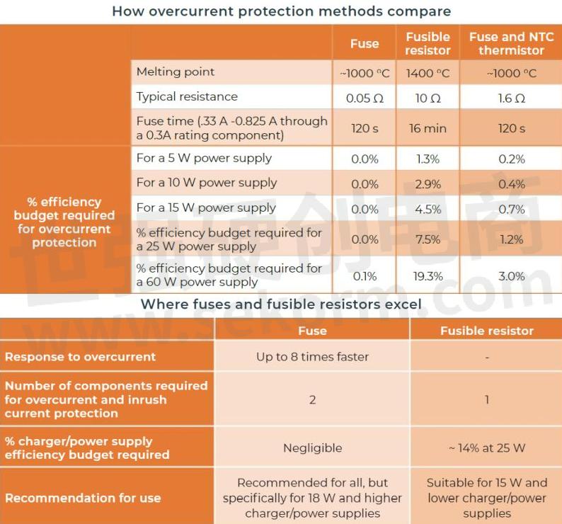
Top, performance comparison of a fuse, fusible resistor, and a fuse with an NTC thermistor in a nominally efficient, charger/power supply circuit. Below, fuse vs fusible resistor and when each component is recommended.
A fusible resistor opens like a fuse when its current rating is exceeded. The component is generally a nichrome element with a melting temperature of around 1,400°C. Nichrome has a low thermal coefficient of resistance which allows the resistor to have a stable resistance over temperature. The 1,400°C melting temperature heats up surrounding components and the PCB during an overcurrent condition.
Fuses are generally copper or silver elements with a melting temperature typically between 962°C and 1,083°C. Fuses also have a high thermal coefficient of resistance, at least a factor of 10 higher than a nichrome fusible resistor. Thus, the temperature of a fuse will rise faster during an overcurrent condition. The fuse resistance rises to bring the fuse to its melting point sooner. A fuse will prevent a heat build-up that happens when a fusible resistor experiences an overcurrent condition. The higher heat generated by the fusible resistor can damage other components and potentially lead to the ignition of nearby combustible components.
The primary benefit of a fusible resistor is that its resistance limits inrush current. A fusible resistor that serves as the main overcurrent component in a power supply or charger can have a resistance of 10 Ω. A fuse, in contrast, has a resistance ranging from milliohms to hundreds of milliohms. Designers can combine a fuse with an NTC thermistor to protect against overcurrents and limit inrush current. An NTC thermistor has a resistance that can be as high as 10 or 20 Ω initially; however, it falls into the tens of milliohms range during steady-state operation.
The fusible resistor seems to save space compared to a separate fuse and thermistor; however, the heat a fusible resistor generates could force components to be kept at least a half-inch away from fusible resistors rated up to 10 W and as much as an inch away from fusible resistors rated above 10 W. When chargers and power supplies must fit in cramped quarters, the component spacing associated with fusible resistors could be problematic.
Efficiency standards
Government efficiency standards for power sources between 2007 and 2018.
Perhaps the most difficult challenge facing designers of power supplies or chargers is mandated efficiency standards. Efficiency standards such as Energy Star and Directive 2009/125/EC Ecodesign have become more demanding over the years. The higher the power output of the supply or charger, the higher the mandated efficiency. The efficiency requirements for three widely used levels of power output are:
60-W supplies and chargers must be 89% efficient
25-W supplies must be 86% efficient
5-W supplies can be less than 80% efficient.
Fusible resistors impact power efficiency because their resistance greatly exceeds that of a fuse. For example, consider a power supply rated at 25 W. Its required efficiency is 86%. The supply’s input power is 29 W (25 W/0.86). Thus, the supply can consume 4 W, its loss budget. A 10-Ω fusible resistor in the circuit can consume 0.59 W (I2R = (29 W/120 V)2 x 10 Ω) which is 14% of the loss budget. That leaves little room for losses in the active components such as the power transistors . A fuse with its milliohm-level resistance would consume a negligible portion of the loss budget, giving the designer more freedom with the development of the complete circuit.

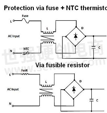
Top, an example of a power supply/charger circuit using a fuse for overcurrent protection and an NTC thermistor to limit inrush current. Below, the same circuit with a fusible resistor for overcurrent protection and to limit inrush current.
Fuses and fusible resistors have different overcurrent and temperature-rise standards. Designers must be aware of the standards that apply to each device. Fuses for the North American markets are evaluated to the requirements of UL/CSA/ANCE Standards 248-1 and 248-14. For the European and international markets, fuses are evaluated to IEC Standard 60127-1 and either IEC Standards 60127-2, -3, -4 or -7.
Different industry standards apply to fusible resistors. For North America, fusible resistors must comply with UL 1412 (in which the component is called a fusing resistor) and CSA Standard C22.2 No. 60065-03. For Europe and international markets, fusible resistors must comply with IEC 60127-8 (in which the component is described as a fuse resistor).

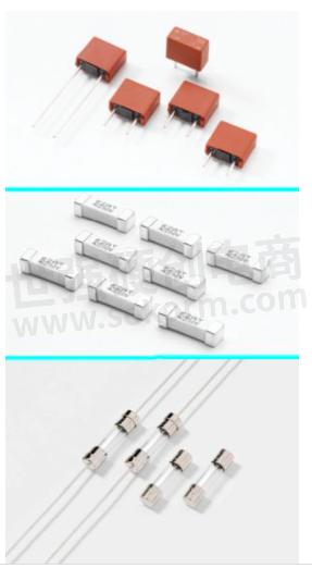
Examples of widely used fuses for overcurrent protection include the 8.5×4-mm 369 Series Radial Lead Fuses (top) with a 300-V rating, a time delay, and open time of 120 sec maximum at a 210% overload; (middle) the 10×3-mm 443 Series Surface Mount Fuses with a 250-V rating and a slow-blow action as well as an open time of 120 sec maximum at a 250% overload; and (bottom) the 20×5-mm 219XA Series Glass Body Cartridge Fuses with a 250-V rating and a slow-blow quality as well as an open time of 120 sec maximum at a 210% overload.
Standards for fuses are quite specific with regard to requirements for an allowable temperature rise. Fuses based on the North American standards UL/CSA/ANCE 248-1 and 248-14 can have a maximum temperature rise of 75°C during temperature testing. The test takes place at room temperature, typically 25°C. Hence the maximum fuse temperature is 100°C, and the fuse must remain intact during the test.
For fusible resistors, UL 1412 does not define a maximum temperature rise. Instead, they are tested by gradually increasing the current through the component until it opens. Cheesecloth either surrounds the fusible resistor or sits at a specific distance from the component. The passing criteria is that the cheesecloth does not ignite. Cheesecloth, constructed from cotton, has an ignition temperature of about 400°C. Thus, the standards for a fusible resistor allow the component to operate at much higher temperatures than those for a fuse.
Recommended use
Fuses must comply with more rigorous standards and, as a result, perform much better than fusible resistors as overcurrent protection components. Because fusible resistors can be a source of ignition without sufficient spacing, they best serve in lower wattage power supplies and chargers likely to experience lower overcurrents and temperature rises. Fusible resistors generally provide suitable overcurrent protection for power supplies and chargers sized up to about 15 W. Higher wattage devices are usually best served by a fuse or a fuse and an NTC thermistor.
- +1 Like
- Add to Favorites
Recommend
- Very Fast Acting Fuse PICO® II Fuse Series, Designed for Battery Management System | Littelfuse
- Littelfuse Launches 1500 Volt Solar String Fuse and Holder Rated 35 to 60 Amperage
- New Littelfuse 400PV Photovoltaic Fuses Provide Rugged Circuit Protection for Next-Gen Integrated Solar Shingles
- Littelfuse Completes Acquisition of C&K Switches
- Littelfuse expands its fuse manufacturing operation in China, Cuting Customer Order Fulfillment Lead Time by Half
- Littelfuse Launches Microsite to Protect Electrical Systems, Motors, and Pumps in Mining Applications
- Littelfuse EV1K Series Fuse First to Provide 1000Vdc Automotive Grade Protection for Next-Gen Passenger Cars and Commercial EVs
- Littelfuse IX4351NE SiC MOSFET & IGBT Driver Wins Annual Power Product Award
This document is provided by Sekorm Platform for VIP exclusive service. The copyright is owned by Sekorm. Without authorization, any medias, websites or individual are not allowed to reprint. When authorizing the reprint, the link of www.sekorm.com must be indicated.


