New Sensor Probes for Optical Blade-tip Timing Measurement Method in Turbine Engines | LEONI

When used in optical blade-tip timing (BTT) measurement techniques, the latest sensor probes from LEONI are not only able to measure blade vibration but can now do so with larger spacing between turbine blades and the engine housing.
The LEONI sensor probes also operate in an environment with high pressures and temperatures in excess of 1,000 °C. The optical fiber connecting the probe tip to the measuring device can also be equipped with a vacuum feedthrough if required. This feedthrough enables the probe to be positioned in a different, harsher environment than the measurement device.
High-speed turbine blades often experience fatigue resulting from excessive blade vibration. These vibrations—and synchronous vibrations in particular—often cause damage to the turbine. Blade-tip timing methods have developed into an established technique for avoiding this kind of expensive damage. Earlier BTT systems required strain gauges and other contact-based methods. Today’s optical BTT techniques now enable contactless measurements that are more accurate & easier to use, offering greater benefits for the manufacturers of turbine engines, such as those used in aircraft.
Optical BTT measurement methods have very demanding technical requirements, however, while also needing robust mechanical components and involving an inherently complex installation. The final set of tests run on new turbine engines often includes vibration measurement for the blades under simulated “real-world” conditions at high pressures and temperatures.
As a design partner for manufacturers of turbine engines used in aerospace, power generation and other industrial applications, LEONI offers fiber-optic sensor probes and bundles that are typically deployed in turbine blade-tip timing measurement systems. This process involves deploying multiple probes for each test rig, each of which potentially contains bundles of hundreds of optical fibers whose individual length may equal or exceed 20m. The probe tips need to meet various requirements depending on the test rig and may need to be straight, curved, flexible for bending at installation, or designed to operate under high temperature and pressure. Other test methods require vacuum feedthroughs.

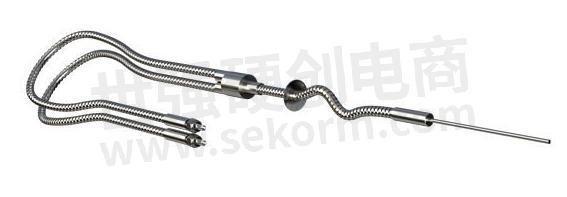
LEONI Optical Blade Tip Timing Sensor Probe Straight with Vacuum Feedthrough

LEONI Optical Blade Tip Timing Sensor Probe Curved

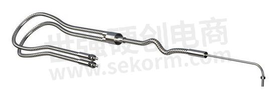
LEONI Optical Blade Tip Timing Sensor Probe 90 Degrees
LEONI Optical Blade Tip Timing Sensor Probe 90 Degrees
LEONI Fiber Optics, Inc. works closely with end users in developing customer-specific probe designs with application-specific fiber arrangements & fiber mapping to ensure the probes can meet demanding requirements of temperature, vibration, pressure, and installation robustness. These designs allow us to accommodate optical measurements in various test rig setups from any turbine manufacturer. Optical sampling data analysis then provides a clear indication of vibration problems as well as blade underrun or overrun, which can avoid potentially extensive and expensive damage.
Our Strengths – Your Advantage:
In designing and building ready-to-deploy fiber-optic assemblies (from the simplest patchcord to BTT probes and complicated mapped bundles), LEONI Fiber Optics, Inc. draws on extensive engineering experience and a broad portfolio of fibers—from borosilicate to metal-coated and other specialty fibers—protective tubes, custom designed ferrules & probe tips, and various connectors.
For over 15 years, LEONI Fiber Optics has been a trusted supplier of solutions to turbine and aircraft engine makers for the special challenges posed by optical BTT measurement. LEONI Fiber Optics, Inc. is both ISO 9001:2015 and ITAR certified.
Applications and industries
Aerospace
Energy/Utilities
Infrastructure
Factory automation
Shipping
Transportation
Industrial turbines and engines
Gas and diesel turbines
Turbines for power generation
- +1 Like
- Add to Favorites
Recommend
- The Principle of Optical Liquid Level Sensor
- Selection and Detection of Fiber Optic Patch Cord
- II-VI Incorporated Introduces Optical Monitoring System for Optical Transport and Access Networks
- PLC Optical Splitter vs FBT Optical Splitter: What‘s the Difference?
- The Difference Between 100G QSFP28 Fiber Optical Transceiver and 100G CFP4 Fiber Optical Transceiver
- Comparison between AOC (Active Optical Cables) and Optical Transceivers
- Why Fiber Optic Attenuators Are Used in Fiber Optic Cable Transmission Lines?
- What Are the Common Fiber Optic Attenuators?
This document is provided by Sekorm Platform for VIP exclusive service. The copyright is owned by Sekorm. Without authorization, any medias, websites or individual are not allowed to reprint. When authorizing the reprint, the link of www.sekorm.com must be indicated.


