How does RF power measurement work?
Keysight tells about How does RF power measurement work? The science of measuring RF power is surprisingly complicated considering that power measurement for most direct current (DC) circuits is relatively simple. You measure the voltage and the current through the circuit, and the product of the two numbers is the power. This simple formula holds true for direct current, but all bets are off when the voltage is alternating, and the load has a reactive component. The complex relationship among the alternating voltage, current, and reactive load, which are all properties of an RF circuit, means that you need a specialized sensor and a meter intended for RF power measurement.
RF power unit
Continuing the comparison with the DC circuit, the unit of power in electrical circuits is the watt (W). This unit is impractical in RF engineering because the orders of magnitude between transmitter and receiver power can be as high as 12. RF Power measurement uses logarithmic unit dBm, where dBm=10log10(Power/0.001 W). To illustrate the point, 0 dBm equals 1 mW which would be the typical transmission power of an Internet of Things (IoT) device. In contrast, an AM radio station can transmit at 50 kW or 77 dBm. Advanced RF applications like satellite and radar must deal with an even greater power range.
RF power measurement
So how do you measure RF power? There are two fundamental interfaces for measuring RF power, conducted and over-the-air (OTA).
Conducted measurement typically uses a coaxial cable with a matching impedance network between the device under test (DUT) and the instrument. This method is far more common since it offers convenience, repeatability, and accuracy. Our discussion will focus on conducted measurement.
OTA, as the name implies, measures the radiated RF power through free space or waveguide using an antenna. OTA testing is increasingly important to support the measurement of the beamforming antennas used in the latest 5G and Wi-Fi applications. Figure 1 shows an anechoic chamber used in OTA testing of 5G millimeter-wave equipment.
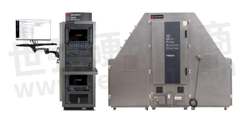
Figure 1. An anechoic chamber for OTA testing of 5G millimeter-wave equipment
The RF power instrument comprises a power sensor and a power meter. The power sensor is the device that interfaces with the RF signal, and the power meter measures the output from the power sensor. The meter provides the user interface for configuring and displaying the measurement. Figure 2 shows a typical setup. The trigger signals are used to repeat the measurements for averaging and time-gating.

Figure 2. RF power instrument setup
The power sensor is not integrated with the power meter to allow flexibility in using different power sensors that suit the application. We will expand on this later. The user can configure the meter for calibration, zeroing, and specifying the parameters of the measurement type. The measurement type can be the average, time-gated, peak, and peak-to-average power ratio (PAPR). The importance of these measurement types depends on the RF modulation scheme, frequency, and dynamic range. RAPR is important for ensuring a low bit error rate (BER) in applications that use digital vector modulations, such as 5G.
RF power sensor
You may be wondering what's inside the power sensor. The first part of the power sensor is the impedance matching load (50Ω) which connects to the RF signal. The load absorbs the RF signal and dissipates the energy as heat. For this reason, the power rating of the sensor should always exceed the power you are measuring to avoid damaging the sensor. A power attenuator can be used to extend the power range but at the expense of performance.
The second part of the power sensor is where the actual power measurement occurs. The two commonly used techniques in RF power sensing are thermal and diode. The thermal method uses a thermocouple or a thermistor that couples closely to the 50Ω load to measure the temperature. Since all the RF energy converts to heat, this is an accurate method for measuring the true average RF power, independent of the modulation. It exhibits excellent accuracy and linearity but suffers from a slow response time, which limits a direct measurement of RF pulse in applications like radar. One benefit of a thermocouple over a thermistor is its faster response time. Figure 3 shows a simplified schematic of the thermal sensors.
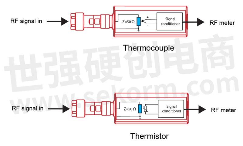
Figure 3. Thermal sensors
The diode method uses high-speed diodes or stacked high-speed diodes to rectify the voltage across the internal load. The rectified voltage is the DC representation of the voltage across the 50Ω load, so using the formula P=V^2/R, the power meter can calculate the power. When the RF signal is low enough to be in the square-law region of the diode, the rectified voltage is directly proportional to the power and yields a very low distortion.
The other regions of the diode require corrections by the power meter which can introduce errors if the RF modulation has a high crest factor. Stacked diodes improve on this limitation by extending the distortion-free region. The diode sensor is well suited for measuring low signals and applications that require a fast response time to measure peak power and PAPR. Figure 4 shows a simplified schematic of diode sensors
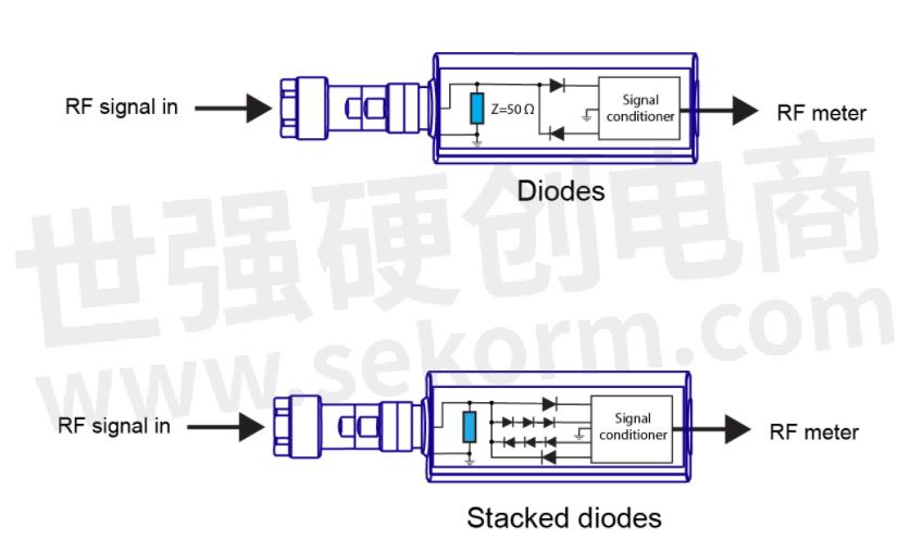
Figure 4. Diode Sensors
You should now understand how RF power measurement works. Although there are modules and portable devices that integrate both the power sensor and power meter, and interface using USB or LAN, the fundamental theory of operation remains the same.
Dalberg-Acton's prophetic words may not be true for RF power, but inadequate power can absolutely cause data corruption through signal compression, something that Marconi would have discovered in his pioneering work.
- +1 Like
- Add to Favorites
Recommend
- RF-STAR Low Power Consumption BLE RF Modules RF-BM-ND05 Based on NRF52840 Chip
- UMS‘ Latest Power Transistor CHK5010-99F with a Wide Band Capabilities up to 12GHz for RF Power Applications
- Keysight Extends Collaboration with Synopsys to Validate Complex RF and Millimeter Wave Design
- Nanochap Stim Engines ENS001 on the Finger Function Rehabilitation Instrument, Any Current can be Programmed to Achieve a High Degree of Product Customization
- How to Improve The Efficiency of Transformer Measuring Instrument
- Triumph Motorcycles Launches Speed Triple 1200 RS and Chooses MTA for the Supply of A State-of-the Art Instrument Display
- Renesas Develops Bluetooth Low Energy RF Transceiver Technologies that Simplify Board Design, Reduce Circuit Size and Increase Power Efficiency
- Renesas Expands RF Portfolio to Cover Complete Signal Chain for Macro Base Stations
This document is provided by Sekorm Platform for VIP exclusive service. The copyright is owned by Sekorm. Without authorization, any medias, websites or individual are not allowed to reprint. When authorizing the reprint, the link of www.sekorm.com must be indicated.
Integrated Circuits


Discrete Components


Connectors & Structural Components


Assembly UnitModules & Accessories


Power Supplies & Power Modules


Electronic Materials


Instrumentation & Test Kit


Electrical Tools & Materials


Mechatronics


Processing & Customization


