2.4GHz SiP Modules Is Ideal for Miniaturized Designs | Silicon Labs
Wireless modules commonly work great on an evaluation board, but when placed into an application design the range is poor. Silicon Labs has taken big steps at mitigating these problems in our BGM12x and the BGM11S SiP modules. In this whitepaper, we explain the technical reasons why the SiP module is ideal for miniaturized designs.
Despite the fact that antennas are complicated and never ideal, major problems can usually be avoided by strictly following the guidelines set forth in the related user manual.
But even with recommendations followed to the letter the multitude of different variables in the design can still cause significant degredation of performance. There are also designs in which it is simply not possible to follow all of the guidelines. Often the only way to improve performance is to modify the entire design, causing a delay in the time-to-market schedule.
Antenna Resonance
When using an SoC with an antenna matched for the actual end-application design, an experienced designer can meet the required performance and cost goals. The frequency of the guitar string can be tuned by increasing theforce pulling on it. Similarly, the resonant frequency of an antenna depends on its size and electromagnetic properties, but can also be tuned by adding suitable components. All antennas have a limited frequency range centered around the resonant frequency. With wider bandwidth, the antenna dimensions become less critical and the antenna becomes less sensitive to detuning caused by resonant frequency shifting.
Antenna Return Loss
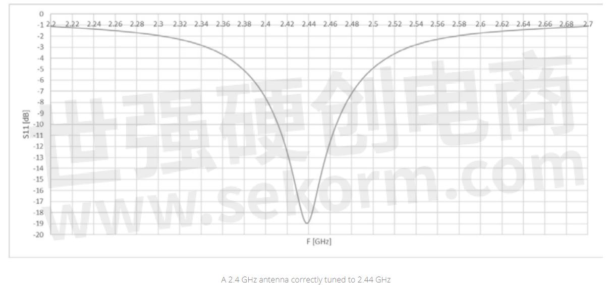
Antenna return loss (also called S11) is a measure of how much of the RF power from the transmitter is transferred into the antenna rather than reflected back at the desired frequency range. The more power reflected due to antenna mismatch, the less power will be radiated by the antenna. The antenna is never perfectly matched, but can usually be optimized for minimal losses at the resonance frequency of the antenna. When the resonant frequency of the antenna shifts away from the desired application frequency, the return loss at the application frequency will worsen with less power being passed into the antenna, which decreases range.

Antenna Robustness
A real antenna resonates as a result of a complicated distribution of electromagnetic fields, where everything in close proximity to the antenna has an effect on the fields and will have some effect on the total operation. The closer an object is to the antenna, the more effect it will have, while the magnitude of the effect for different materials varies. Conductive objects such as metals have a very strong effect, while plastics have a fairly weak effect. However, even plastic placed very close to the antenna can produce a significant effect by shifting the antenna resonant frequency. This results in a low return loss and a corresponding reduction of the radio link range.
In RF modules, the antenna is typically tuned for optimal performance based on a representative application board, with no enclosure material in the immediate proximity of the antenna. When the RF module is placed on an actual customer application board, the size, shape, and material properties - and possibly also the thickness of the board - will be different than those of the representative application board. In addition, the board is typically placed into an enclosure made of some sort of plastic. As a result, the antenna will behave differently compared to the representative application board for which the antenna was optimized. The impact of the proximity of various objects and materials have on the antenna is an important factor in selecting the antenna.
In RF modules, the antenna is typically tuned for optimal performance based on a representative
application board, with no enclosure material in the immediate proximity of the antenna.
SoC vs. Module?
When using an SoC with an antenna matched for the actual end-application design, an experienced designer can meet the required performance and cost goals. The optimization of antenna performance and the SoC RF layout requires understanding of RF design rules and quite expensive equipment. As the number of wireless applications and devices increases, the required regulatory certification may become too expensive and time-consuming. This is especially true when the product portfolio increases to tens or even hundreds of devices each requiring separate certification-related product management. The solution becoming increasingly popular is to utilize ready-made, pre certified, ready-to-use wireless modules, especially for IoT related designs.
In RF modules, the arduous task of antenna matching has been done with no application-specific tuning necessary in most cases. However, sometimes the end product design cannot avoid the placement of an attachment screw, LCD, or battery close to the antenna, which causes significant changes in the antenna resonant frequency and overall performance. The modules themselves cannot be easily modified to compensate for the detuning.
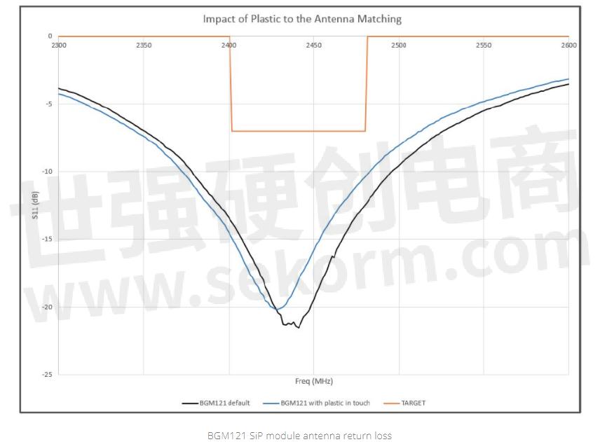
An example of the impact a plastic material placed on top of a monopole type chip antenna is shown in the figure below. The plastic material on top of the antenna clearly shifts the resonant frequency and moves it out of the target frequency range. The problem regarding compensation is that with a typical module the matching components areinside the module making adjustment impractical.

Often an external antenna can be used with a module. This is still easier than the total design effort of using an SoCand includes the certifications when the selected antenna is chosen from the list of accepted antennas included in the certification reports. An external antenna, either with a connector or a ceramic chip antenna, provides more flexibility regarding the placement of the antenna and its performance. However, matching the impedance of an external antenna is quite difficult and requires expensive equipment. An improved level of flexibility is provided by SiP (Systemin-Package) modules where the small size allows a part of the antenna structure to be placed outside of the module. This typically consists of a short copper trace, the dimensions of which can, in most cases, be copied from the manufacturer’s datasheet recommendations. The resonant frequency of the antenna depends to some extent on the actual length of this external track. Thus, the detuning effect caused by objects near the antenna can be compensated simply by adjusting the length of the external copper trace. This provides an effective method for detuning compensation without adding a single item to the BOM list.
Silicon Labs SiP Antenna Robustness
The proximity of any material will always have some effect on the resonant frequency of the antenna. The strength of this effect depends on the actual antenna model used. Silicon Labs has an antenna solution for SiP modules (patent pending) which minimizes the required total size of the antenna while still making the antenna exceptionally insensitive against the effects from nearby objects. Any plastic object can be placed as close to the modules as necessary without a need to re-tune the antenna, including full overmold with protective conformal coating or epoxy mass. High performance is possible even with a metallic object touching the module, which is impossible with almost any other RF module with an integrated antenna (although such a setup may need some antenna re-tuning for optimal performance).
BGM121/123/11S – Unique Wireless SiP Modules
Silicon Labs SiP modules are exceptional in many ways and the features implemented into the module design are addressing all of the concerns mentioned above. For example, unlike any other modules in the world, BGM121,BGM123 and BGM11S provide as high antenna efficiency as can possibly be achieved with any passive antenna.These modules are practically immune to any dielectric close to or in touch with the module. Thus the thickness of the application board PCB, conformal coating, plastic casing or any kind of molding on top of the module do not have asignificant negative impact on the RF performance of the module.
When in close proximity to a metallic object, even the BGM121/123/11S module will experience some detuning. In these cases the modules can be easily tuned externally by adjusting the width of the antenna clearance area (see the figure below). This allows placing the module into any kind of mechanical design, even with a battery or display under the antenna area while still achieving the highest possible radiated performance. There are no restrictions whatsoever where these modules can be used as long as they are not entirely surrounded by metal, which would prevent RF radiation.The detuning for the above listed modules is done simply by adding a suitably dimensioned Clearance Area (a copperfree area on the PCB) as indicated in the example figure below, which shows the Clearance area dimensions for BGM11S (for a more detailed description see reference [2]).

The shape of the radiation pattern (see figure below) is not dependent on the shape of the application PCB. BGM121has a nice omnidirectional radiation pattern in all designs and thus provides reliable operation in Bluetooth applications regardless of the PCB design surrounding the module.

Comparing the total radiated efficiency of BGM121 SiP module containing the specially selected internal chip antenna with some competitive solutions clearly shows the advantage gained by using the Silicon Labs solution as shown in the figure on the following page.

Conclusion
SiP modules provide space and cost savings but their built-in antennas are prone to detuning in real applications.Proper design can help minimize adverse effects to some degree. The method described here based on the use ofthe copper clearance area for compensating antenna detuning is a simple and economical, yet an extremely powerful solution for detuning compensation.
- +1 Like
- Add to Favorites
Recommend
- Silicon Labs Simplifies IoT Development with Simplicity Studio 5
- Silicon Labs Strengthens Isolated Gate Driver Portfolio
- Software Speeds Development of IEEE 1588 System Integration | Silicon Labs
- Filo Leverages Silicon Labs Bluetooth Modules for Life-Saving Baby Car Seat Alarm
- News | Silicon Labs and Amazon Collaborate on Sidewalk, a New Shared Network for IoT Consumer Devices
- Silicon Labs Expands Isolated Gate Driver Product Family Ideal for Hybrid and Electric Vehicles (EV)
- Silicon Labs and Skyworks reach agreement to sell infrastructure and automotive business
- Fighting COVID-19: Maggy Chooses Silicon Labs‘ Bluetooth SiP to Develop a Wearable Social Distancing Device
This document is provided by Sekorm Platform for VIP exclusive service. The copyright is owned by Sekorm. Without authorization, any medias, websites or individual are not allowed to reprint. When authorizing the reprint, the link of www.sekorm.com must be indicated.


