Testing LED using PathWave Test Executive for Manufacturing
Light-emitting diodes (LED) gained massive adoption in the past decade, replacing conventional incandescent lighting methods which consume more power. Today, LED is used in a wide range of applications ranging from small optical sensors to large billboard displays on buildings. LED emits light ranging from the invisible spectrum to the visible spectrum. Infra-red sensors or camera systems are some of the applications that use LED on the invisible spectrum, while visible spectrum LED is used primarily for lighting or display purposes.
The automotive industry uses LED for headlights, signaling, dashboard, and cabin lighting. Traditional automotive lighting is controlled by mechanical relays to turn them on or off. However, in today’s automotive environment, a set of headlights doesn’t simply switch between on and off. Lighting sequences and requirements are much more complicated with the increased level of intelligence put into a vehicle. Working together with a range of sensors installed around the car, your car may decide to adjust the level of brightness and color of the headlights as you drive through different environments on the road. This calls for a more sophisticated method of testing to ensure that the automotive lighting assemblies in your car work as expected.
The standard in-circuit test measures each of the LEDs for their values and orientations. While this is sufficient to guarantee that each LED is good, more is needed to ensure the functionality of the product as a whole. With PathWave Test Executive for Manufacturing(PTEM), you can develop customized test sequences that test the actual functionality of the full assembly.
LED Analyzer
PTEM supports the Feasa LED Analyzer module, one of the popular LED test solutions available in the market. PTEM supports the 5 and 20 channels modules so you can mix and match the types of modules to cater to different test channel configurations. To facilitate the assignment of analyzers within a PTEM test plan, PTEM separates the serial COM port definition from the analyzer’s definition. You can have one COM port assigned with multiple analyzers in a daisy-chained setup or one COM port for each analyzer for a standalone setup.

Figure 1: Daisy-chained analyzer modules use one serial COM port for control
LED Spec Editor
The LED spec editor table holds the details of the LEDs to be tested. This is where you set up a relationship map between the LEDs and their analyzer modules. LEDs can be organized into groups so that you can selectively choose which group of LEDs you want to test. A group is the highest in the test hierarchy. It can have multiple LEDs assigned with different analyzer modules from different boards. When a group is tested, PTEM gets the list of the LED defined under the group and automatically sends the trigger to all the analyzers involved.
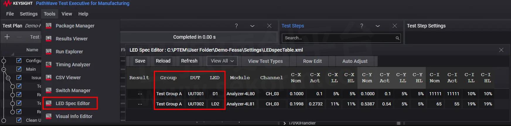
Figure 2: LED spec editor maps LED to analyzer's channel number
In Figure 2 above, Test Group A consists of two LEDs from different boards, each assigned to a different analyzer. When a test calls for this group, PTEM will trigger analyzers 4L80 and 4L81 to make the measurement. This makes things a lot easier as you only need to decide which LED to test and not worry about which LED uses which analyzers.
Next in the hierarchy is the board. Similar to the concept of a group, multiple LEDs on a board can also be assigned to different analyzers. During runtime, PTEM automatically sorts out the linkage between the LED and the respective analyzers and triggers them for measurement accordingly.
The lowest level in the hierarchy is the LED part itself. This targets specifically to the LED part name of any board so you can create a test specifically for each LED if needed.
The measurements from the test are updated in the table after each execution so that you can easily monitor the results for troubleshooting. Based on the limits defined in the table for each test, PTEM updates the result column with the pass/fail value. You can use the Retrieve test step to get the result value and perform pass/fail judgment with the limit check test step accordingly.
Test measurement
There are many different ways you can test an LED. Depending on the application of the product, testing methods and criteria vary. LED used for lighting products are tested for brightness, but not necessarily color whereas LED in graphical display applications will test for its color as well.
Chromaticity (CxCy), Hue, Saturation, Intensity (HSI), Red, Green, and Blue components (RGB), and Wavelength (Wavelength) are different types of measurement methods that represent the brightness and color of an LED. Depending on your preference, you can choose which measurement methods to use. Applications with stringent criteria on the LED’s color may choose to do an RGB test as each color component is represented individually. For other applications without strict color requirements, the wavelength test provides a quick measurement of the color. All the tests also report a value to represent intensity, which is the brightness of the LED.

Figure 3: Measurement units for LED test in PTEM
Four test steps are provided in PTEM, each for a type of measurement. You can selectively choose the test that you need and add them to the test plan. The test step allows you to define which group, board or LED you like to test.
Issue Capture
Ideally, you want to light up all LEDs at once and test them together. This reduces test time significantly compared to lighting and testing them sequentially. Once the LEDs are lighted up, you execute the Issue Capture test step to capture the measurements with the analyzers. Some applications may only allow you to light up some LEDs at the same time because of circuit restrictions or proximity between LEDs which may lead to light interference in the measurement. In cases like these, you separate the LEDs into different groups and test each group sequentially under its own Issue Capture test step.
When PTEM executes the test, it consolidates the list of selected LEDs from the child steps structured under the Issue Capture step. In Figure 4 below, the Issue Capture step contains two child steps which are Test Wavelength and Test CxCy. Based on the LED selected in these test steps, PTEM sends the trigger to the respective analyzers concurrently to make the measurements.
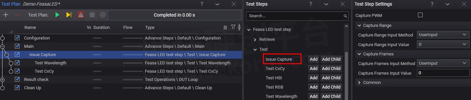
Figure 4: Issue Capture step triggers analyzers to capture measurements
Measured values are updated in the LED spec editor table after each Issue Capture step execution. PTEM tests the measured value against the limits set in the table and places the result into the Result column. There are multiple values for each type of test, and as long as one of the values goes beyond the limits, that LED will be considered to fail. In Figure 5 below, the chromaticity test contains a total of 3 values, namely C-X and C-Y for color, and C-I for intensity. All these values must stay within the limits for the test to pass.

Figure 5: Measurement is updated into the LED spec editor table after each capture
Retrieve
Retrieve test steps allow you to read individual LED test result and process it at the test plan to determine the final pass/fail of the board that the LED belongs to. Other than the test result value, you can also get the measured value of color and intensity as well. This is useful when you want to use the values for further decision-making in the test plan.
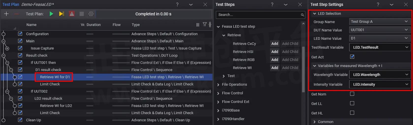
Figure 6: Retrieve step returns the test values of LED from the LED spec editor
In Figure 6 above, the Retrieve step for device D1 of UUT001 returns the test results along with the actual measured value of wavelength and intensity to the test plan. Nominal (Nom), low limits (LL), and high limits (HL) values are not selected in the example. The Limit Check test step below the Retrieve step checks the test result value and sets the pass/fail flag of UUT001 in the test plan.
Overall, the integration of Feasa’s LED analyzer into PTEM is simple and easy with the low-level commands of the analyzers built into PTEM’s test steps. Creating test steps for individual LEDs is tedious and time-consuming. The LED spec editor lets you set up the mapping between the LED, board, and analyzers easily so that you can simply select groups or individual LEDs to test in the test plan.
- +1 Like
- Add to Favorites
Recommend
- Keysight i7090 with PTEM – Auto Mode Operation
- Keysight i7090 with PTEM – System Initialization
- Keysight Technologies Acquires Quantum Benchmar, Augmenting Keysight‘s Quantum Portfolio
- Keysight First to Gain GCF Approval of Cases for Validating 5G New Radio mmWave Devices in Standalone Mode
- Keysight‘s O-RAN Test Solutions Enable Xilinx to Accelerate Development of Massive MIMO Radio Reference Design
- Keysight and Transphorm Create Power Supply Reference Design that Lowers Product Costs; Speeds Time to Market
- Keysight Massively Parallel Board Test System Selected by LACROIX in Automotive Printed Circuit Board Manufacturing
- Keysight, TIM and JMA Wireless Join Forces to Showcase O-RAN Technology at Mobile World Congress 2021
This document is provided by Sekorm Platform for VIP exclusive service. The copyright is owned by Sekorm. Without authorization, any medias, websites or individual are not allowed to reprint. When authorizing the reprint, the link of www.sekorm.com must be indicated.
Integrated Circuits


Discrete Components


Connectors & Structural Components


Assembly UnitModules & Accessories


Power Supplies & Power Modules


Electronic Materials


Instrumentation & Test Kit


Electrical Tools & Materials


Mechatronics


Processing & Customization


