Keysight i7090 with PTEM – Auto Mode Operation

An automated inline handler system minimizes human involvement in the handling of the product through a manufacturing production line. This improves efficiency and guarantees consistency in the quality of the product as it removes the ambiguity of human judgments and prejudice. Balancing the beat rate of different systems in a production line decides how efficient the manufacturing process will be. The key is to distribute the workload among the different machines or testers along the production line such that all of them work at the same beat rate. With the Keysight i7090 automated inline test system and Pathwave Test Executive for Manufacturing (PTEM), you have the flexibility to tailor a test sequence specifically for a product to achieve the best performance.
This post is part of a series of blogs that I am publishing about test automation using Keysight i7090 inline handler with PTEM. The series aims to educate users on the operation of the i7090 handler system and the features of PTEM that support the test integration. If you would like more information on this, do check out the links to related posts at the end of this article.
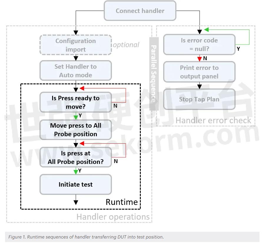
My earlier posts covered configuration import, system auto mode, and handler error monitoring sequences. Figure 1 shows an event flow chart on the transfer of a device under test (DUT) into the test position. Once the handler gets into auto mode operation, the programmable logic controller (PLC) takes over the transfer of the DUT and interacts with PTEM at certain intervals during the operation. Now let us look at the runtime section of the flowchart in Figure 1.

After the handler completes the initialization sequence, the PLC signals the upstream conveyor to transfer the DUT. The DUT travels on the conveyor until it arrives at the stopper position as shown in Figure 2. The figure shows an optional set of stoppers fitted into the i7090 handler allowing it to handle two DUTs at the same time for higher efficiency. Depending on the handler configuration settings, the PLC uses one or two of the stoppers accordingly during the transfer of the DUTs. Sensors along the conveyor rail detect the DUT position so that the PLC knows when to stop running the conveyor belts.

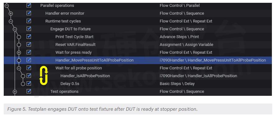
While the handler performs the transfer of the DUT, the PTEM test waits in a repeat loop for the DUT to get into position before sending the command to engage it into the test fixture as shown in Figure 3. Under the Parallel operations section of the test plan, there are two sets of sequences that run in parallel. The handler error monitor checks for any handler errors while Runtime test cycles wait for the DUT to get into position.

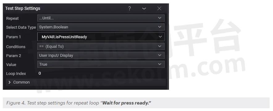
A repeat loop named “Wait for press ready” queries the PLC to check if the DUT is in position using the Handler_IsPressUnitReadyToReceiveMoveCommand step. The test step returns a Boolean value to a variable specified in the field Param1. The loop waits for this value to become True before exiting to the next step.

Within the repeat loop, test plan checks the state of the PLC every 0.5 seconds until it receives an active response from the PLC showing that the DUT is in position. It is important to add a small delay in the loop to prevent memory overflow while waiting for the DUT to arrive. The loop repeats itself until it fulfills the conditions for exit.
Software programming practices discourage the use of open-ended loops. These are loops that will keep going indefinitely if they do not receive the required conditions. Typical practice to prevent infinite looping is to have a predetermined timeout value included in the loop such that it exits the loop when the timeout expires regardless of the conditions.
Although you can set up the repeat loop with a timeout value in PTEM, I do not recommend doing this because it is difficult to estimate the arrival time of the next DUT in a production environment. Sometimes, the wait can range from an hour to the next day, or days.
For the testplan, it does not matter if the loop must wait for a long time for the upstream station to release the DUT, but when it does release the DUT, the testplan must be ready to receive the DUT. By adding a timeout to the loop, you limit the flexibility of the wait duration and the testplan may timeout and stop before the DUT is available. This creates unnecessary downtime to restart the testplan again. So how then can we overcome the infinite loop?
The answer is with the handler error monitoring sequences which runs in parallel with the repeat loop.
When the PLC starts the transfer of the DUT, it goes into an automated sequence to bring the DUT into the stopper position. When an unexpected event obstructs the transfer, PLC will generate an error, which in turn triggers the handler error monitor sequence in the testplan to stop and report the error. So, the infinite repeat loop will never be stuck if the DUT does not get to the stopper position.
With the DUT at the stopper position, testplan executes the next step to engage it onto the test fixture using the Handler_MovePressUnitToAllProbePosition test step.

Testplan now waits for the press to move to the All-Probe position. All Probe position is a parameter in the handler configuration that determines the position of the press when the DUT contacts all the test probes on the fixture.
The “Wait for all probe position” loop uses the Handler_IsAllProbePosition test step to check the engagement action at 0.5 second intervals. Again, there is no need to have a timeout loop for this as the PLC will trigger an error if the operation fails.
Now with the DUT engaged onto the test fixture, testing operations can start. Depending on the test requirements of the DUT, you can perform in-circuit or functional tests and device programming on the DUT.

Table 1 tabulates all the test steps that I have discussed so far in all my posts on automation control of the i7090 system. You can find more information in the related posts below. That is all for now. We will talk about the sequences to send the tested DUT out of the handler in my next post. Till then, feel free to drop me a message if you have any questions.
- +1 Like
- Add to Favorites
Recommend
- Keysight i7090 with PTEM – System Initialization
- Keysight i7090 with PathWave Test Executive for Manufacturing
- Keysight Introduces i7090 Massively Parallel Board Test System Supporting up to 20 Cores
- Keysight Massively Parallel Board Test System Selected by LACROIX in Automotive Printed Circuit Board Manufacturing
- Keysight Technologies Acquires Quantum Benchmar, Augmenting Keysight‘s Quantum Portfolio
- Keysight First to Gain GCF Approval of Cases for Validating 5G New Radio mmWave Devices in Standalone Mode
- Keysight‘s O-RAN Test Solutions Enable Xilinx to Accelerate Development of Massive MIMO Radio Reference Design
- Keysight and Transphorm Create Power Supply Reference Design that Lowers Product Costs; Speeds Time to Market
This document is provided by Sekorm Platform for VIP exclusive service. The copyright is owned by Sekorm. Without authorization, any medias, websites or individual are not allowed to reprint. When authorizing the reprint, the link of www.sekorm.com must be indicated.


