Keysight i7090 with PathWave Test Executive for Manufacturing
Manufacturing environments vary depending on the type of products you are building. While most industries do not require special consideration for their manufacturing space, the automotive industry and bio-medical sector require a higher level of control and cleanliness to their production floor. This is where no-touch manufacturing comes into play.

the author
No-touch manufacturing refers to a manufacturing setup whereby machines assemble and test products in a fully automated production line without operators and technicians. While you may think that having someone to watch over the production line helps, it may not be the case. The truth is that human beings are not consistent in decision-making. Each decision we make is a result of numerous factors and reasoning which includes personal experience and preference. The same problem can receive different solutions when managed by different people.
Physical contamination is another problem. The simple act of picking up a product off the production line and placing it back can introduce unwanted substances like oil and dirt onto the product or risk the misplacement of the product itself. One example is when the operator picks up a product for inspection and places it back on the conveyor line in the wrong orientation. This creates a line-stop scenario and can potentially damage equipment. Handling without proper grounding also results in electrostatic discharge damage to the product.
Minimizing human intervention during production enables the production to operate in a stable and predictable environment. Keysigt’s FlexiCore Parallel ICT system and i7090 Massively Parallel ICT system are automated inline handler systems designed specifically for high throughput automated inline test applications. Both models are supported by PathWave Test Executive for Manufacturing (PTEM) software which allows easy control of the handler’s operation. The automated inline handler operations are segmented into different operating stages with the relevant test steps built into the PTEM libraries. You can control how the handler operates without the need to manage the low-level details of the system’s sensors and drivers.
My earlier posts talk about the control of the FlexiCore Parallel ICT system using PTEM. This post discusses the control for the i7090 Massively parallel ICT system. In PTEM, test steps for the i7090 handler controls are listed under the i7090Base and i7090Handler sections. We just need a few of them to create the testplan for an automated test operation. The rest of the test steps allow you to control the movements of specific mechanisms in the handler manually or to query the states of various sensors.
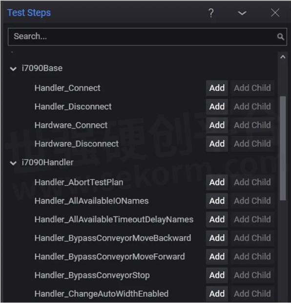
Figure 1: i7090 inline handler control test steps built into PTEM.
Let’s start by creating a sequence to monitor the error state of the handler. Figure 2 below shows a simple flowchart for the sequence. The flow starts with establishing a connection between the handler and PTEM. Once connected, we can query the error code of the handler and report the error state if detected.
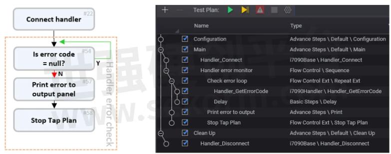
Figure 2: Step sequence for handler error monitoring.
The step sequence in the PTEM testplan starts with the Handler_Connect step under the Main section. This step establishes the link between PTEM and the handler. The next step starts a conditional repeat loop to monitor the value of the error code from the handler.
Handler_GetErrorCode test step returns the value of the error code from the handler. A null value indicates normal operation whereas other values represent an error situation. Once an error is detected, the sequence exits the repeat loop and prints the error message before stopping the testplan execution with the Stop Tap Plan step. Upon stopping of the testplan, PTEM automatically executes the Clean-up section where the Handler_Disconnect step terminates the connection to the handler. This completes the handler error monitoring sequence in the testplan. When there is no error, the sequence continues to loop infinitely while the testplan executes other test operations in parallel.
Now with the error monitoring sequence running, we can start initializing the handler and load the configuration settings. The i7090 system handler supports the import of pre-defined handler configuration files. This allows you to quickly configure the system to match different operation setups like conveyor widths and press heights.
The use of Paralle l test step in PTEM allows multiple sequences to run at the same time. In our case, we keep the error monitoring sequence running in parallel with the other handler operation sequence. In Figure 3, the Parallel sequence group holds the Handler error monitor and Import Handler configuration groups as its child sequences. This creates two parallel running threads so that we continue to monitor for handler errors while importing handler configuration along with other tasks.
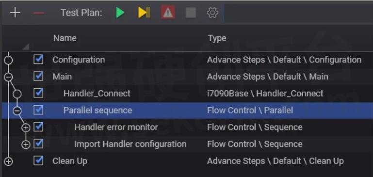
Figure 3: Error monitor and configuration import sequences run in parallel.
The flowchart in Figure 4 shows the sequence of importing handler configuration on the left and the parallel running handler error monitoring sequence on the right. Both sequences start after the connection to the handler is completed. While the error monitor sequence loops, the configuration import sequence loads the configuration file to the handler. Once the configuration is loaded, other sequences can follow while the error monitor sequence continues looping in parallel. We will talk about the other sequences in future posts.
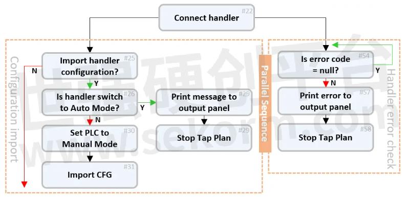
Figure 4: Flowchart of error monitor and configuration import sequence.
Importing of configuration requires the handler to be switched into manual mode. In Figure 5, the beginning of the configuration import sequence checks the state of the handler using the Handler_IsSwitchInAutoMode step. If the return value is true, it indicates that the handler is not in manual mode and testplan prints an error message before terminating. If the return value is false, it means that the handler is correctly switched to manual mode. We then proceed to set the programmable logic controller (PLC) into manual mode with the Handler_SetManualMode step followed by the Handler_ImportSystemHandlerProfile step to import a 450mm single board configuration to the handler.

Figure 5: Testplan sequence to import handler configuration.
At this point, all necessary parameters required for the i7090 inline system have been loaded into the application. The handler is now ready to start the test operation.
Table 1 below provides the list of test steps that I discussed so far in this post. We will continue to add more to the list as we expand further into different test operations.

Table 1: Summary of handler control test steps described in this post.
- +1 Like
- Add to Favorites
Recommend
- Keysight i7090 with PTEM – System Initialization
- Keysight i7090 with PTEM – Auto Mode Operation
- Keysight Introduces i7090 Massively Parallel Board Test System Supporting up to 20 Cores
- Keysight Massively Parallel Board Test System Selected by LACROIX in Automotive Printed Circuit Board Manufacturing
- Keysight Technologies Acquires Quantum Benchmar, Augmenting Keysight‘s Quantum Portfolio
- Keysight First to Gain GCF Approval of Cases for Validating 5G New Radio mmWave Devices in Standalone Mode
- Keysight‘s O-RAN Test Solutions Enable Xilinx to Accelerate Development of Massive MIMO Radio Reference Design
- Keysight and Transphorm Create Power Supply Reference Design that Lowers Product Costs; Speeds Time to Market
This document is provided by Sekorm Platform for VIP exclusive service. The copyright is owned by Sekorm. Without authorization, any medias, websites or individual are not allowed to reprint. When authorizing the reprint, the link of www.sekorm.com must be indicated.
Integrated Circuits


Discrete Components


Connectors & Structural Components


Assembly UnitModules & Accessories


Power Supplies & Power Modules


Electronic Materials


Instrumentation & Test Kit


Electrical Tools & Materials


Mechatronics


Processing & Customization


