The Barb Design of Connector Terminals

Terminals are used in Connector products as bridges for information and current connection. In order to ensure that the terminal is firmly fixed within the housing part, the terminal’s barbed structure and the housing’s interference design are particularly important.
One of the functions of the connector housing is to provide mechanical support, fixing the metal terminals used for connection, which is achieved mainly through terminal barbs and housing interference, making barbs one of the key elements of connector design.

Figure 2 shows the interaction between barbs and housing materials under a microscope. When the pin is inserted, the material will be stacked on both sides and in front. When the pin is in place, the extruded material will bounce back, but the plastic housing can not return to its original state after bouncing back, only allowing for a partial return to its original state, about 0.04mm (interference is 0.07mm). During the withdrawal process, the barb will remove the bouncing material. The material squeezed when the barb is inserted into the end will bounce back when the barb is removed. When the pin is completely removed, the plastic slot fitted with the pin is enlarged for the materials to be removed by the barbs. If the terminal is inserted at this time, the retention force of the pin will be greatly reduced. That is why the used plastic housing cannot be reused.

The retention force is mainly composed of F1 and F2, which is caused by the exclusion of materials. Therefore, the parameters that affect retention force geometrically are A, B, D, E, F, and G.
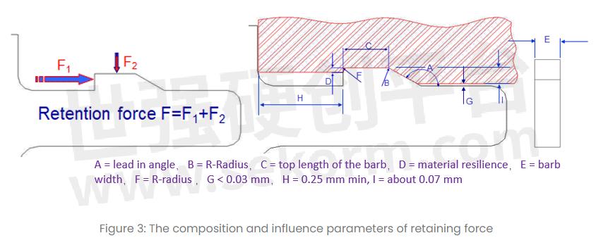
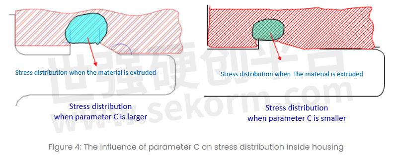
The retention force also has a certain relationship with the interference volume: the larger the interference volume, the greater the retention force. For the same interference height, the interference volume depends on the interference length C. In addition to the influence of parameter C on the retention force, the larger stress area will also cause an increase in the stress distribution area inside the housing and lead to deformation, resulting in cracks in the plastics.
The problems of barb technology used in connectors with thin plastic bodies are discussed in the following sections. Based on two cases, the contact gap between the barb and retaining force/finished product will be discussed. The interference situation was observed by microscope, so as to optimize the main parameters of barb design.
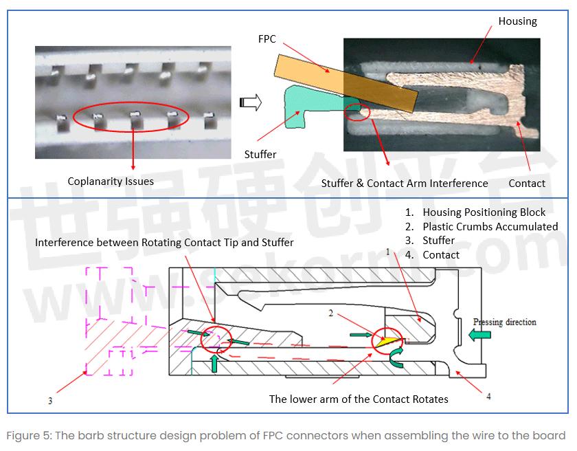
A. The barb structure design problem when assembling the wire and the board, taking the FPC connector as an example:
The connector terminal is located outside of the housing groves, which makes the stuffer bump up against the terminal head when being pushed in--making it difficult to be inserted because of the stuffer's interference with the rotating contact as it advances. The gap between the front end of the contact barb and the housing pinhole is small so, during the process, the plastic scraps accumulate, making the lower arm of the contact rotate. To improve this problem, GREENCONN engineers increased the gap between the front end of the contact and the housing pinhole to accommodate for the plastic chips.
B. The barb structure design problem during the connector assembly process: Gap 1 is, on average, 0.12mm larger than Gap 2. The reason behind this is that the far plastic mouth has a higher amount of contact scraps than the scraps near Gap one, resulting in a slight rotation of the contact (1.02 degrees downward which are about a 0.12mm gap difference)
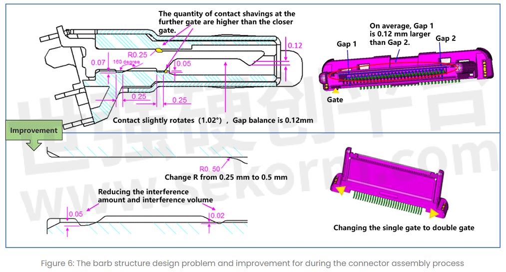
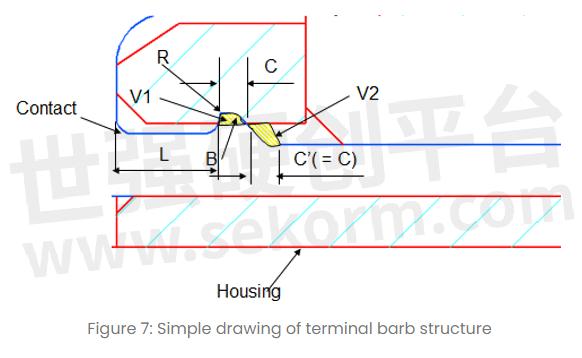
When the contact is inserted during the connector assembly process, the contact barb will cause damage to the housing surface. The weaker the housing strength is, the more serious the damage is. As a result, there is plastic debris and assembly stress, resulting in the occurrence of the "Furrow phenomenon". Therefore, based on practical problems and the parameters affecting retention force, the following suggestions can be taken into consideration when optimizing the barb structure of terminals. Use the figure below as a reference:
1. B: R-radius should be as large as possible
2. V1 must be greater than V2
3. R: Should be as small as possible
4. L: Length should be at least 0.25mm
5. The strength of the housing pinhole and the interference arm of the contact barb should be as even as possible.
6. Should not have any burrs on the contact barb
- +1 Like
- Add to Favorites
Recommend
- Terminal Connection Method of Electrical Connectors
- Kinghelm FFC/FPC Connector KH-FG1.0-H2.0-24PIN High-Performance Connector Solves Your Internal Connection Issues in Electronic Devices
- Advantages of Smiths Interconnect EMI Filter Connector and Filtered EMP Connectors
- Some Common Connection Methods of Industrial Connectors
- In-depth Understanding of the Connection Types of Industrial Connectors
- Kinghelm Type-A Connector KH-CP3.5AF180CB-14JB-STM with USB Connection Standards Leading the Trend of Connectivity
- Kinghelm KH-SIM1616-6PIN MicroSIM Card Connector, A Top-tier Self-ejecting MicroSIM Card Connector Featuring 6 Pins
- Kinghelm‘s VH Connector KH-VH-3P-Z with 3.96mm Pitch Is A High-performance Connectivity Solution Due to Its Reliability and Durability
This document is provided by Sekorm Platform for VIP exclusive service. The copyright is owned by Sekorm. Without authorization, any medias, websites or individual are not allowed to reprint. When authorizing the reprint, the link of www.sekorm.com must be indicated.
Integrated Circuits


Discrete Components


Connectors & Structural Components


Assembly UnitModules & Accessories


Power Supplies & Power Modules


Electronic Materials


Instrumentation & Test Kit


Electrical Tools & Materials


Mechatronics


Processing & Customization


