Radar transceivers: a key component for ADAS & Autonomous Driving-Basics of FMCW radar

1.1 What is radar?
Radar (acronym for Radio Detection and Ranging) uses radio waves to detect objects in the environment. It allows determining the distance (known as range), angular position (bearing), and velocity. Radar technology was developed for military use during World War II, but has now many civil applications, including air or marine traffic control, astronomy, ocean and meteorological monitoring, altimetry, geological observations and automotive applications.
The radar system includes a transmitter, which emits an electromagnetic radiofrequency wave (radar signal) in a certain direction. The signal reflected off the target objects (echo) is then detected by the radar receiver. The magnitude of the reflection is determined by the object’s material properties, size and shape (radar cross section RCS). By processing this reflected signal, the properties of the target can be determined.
1.2 FMCW radar
Automotive radar systems operate using a so-called Frequency Modulated Continuous Wave (FMCW). The system transmits a continuous wave at a certain frequency, which is then modulated over a period of time T. This gives the transmitted signal a “time stamp". The signal travels then to the target and part of it is reflected back. The radar will detect the reflected signal and compare it to the original one by mixing them and processing the resulting signal. A simplified schematic is presented in Figure 1.
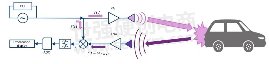
Figure 1: FMCW automotive radar – Principle and building blocks
An example of this radar signal is shown in Figure 2 and Figure 3. The returned signal is similar in shape to the transmitted one, but shifted in time as the two-way trip from the radar to the target takes an amount of time ∆t that is proportional to the distance to the target R:

With c being the light velocity.
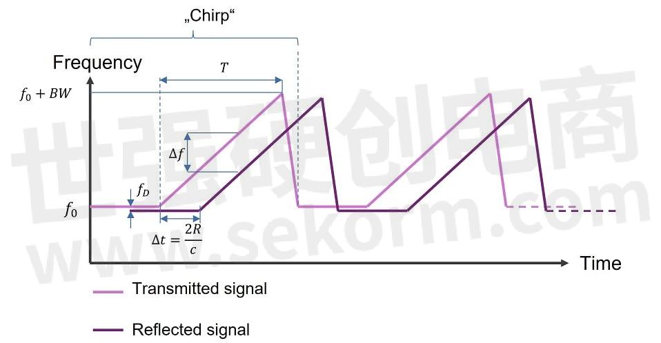
Figure 2: Sawtooth FMCW radar signal: frequency vs. time.
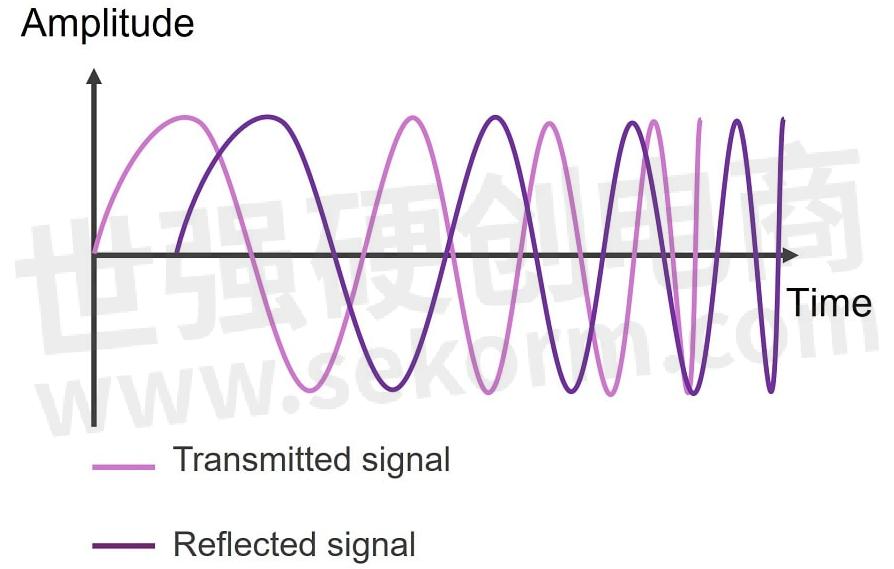
Figure 3: FMCW radar signal: amplitude vs. time.
By comparing the reflected wave with the original signal at any given moment of time, a frequency shift ∆f can be observed. This shift allows determining the range R for each period of the signal or “chirp”. If the signal is monitored over several chirps, an additional frequency shift fD will be detected for a target moving towards or away from the radar, due to the Doppler effect. This allows determining the velocity of the target. Finally, if different channels are considered, using spatially distributed antennas, the direction of arrival of the signal can be established, to obtain the 2D or 3D position of the target.
That means that, to have 4D detection (range, azimuth and elevation direction, and velocity), a space-time processing of the signal is needed. For that, the signal needs to be digitized and saved for further processing. The first step will be creating the so-called “radar cube”.
1.3 Radar processing - The radar cube
The radar data cube is three-dimensional graphic depiction of the space-time processing of the stored radar data. It summarizes the three basic steps required to obtain range, velocity and bearing information.
As mentioned above, the received signal is sampled for processing. The first step is performing an FFT (Fast Fourier Transformation) so that each sample corresponds to a “bin” to obtain the range information over the so-called “fast time”. This is illustrated in Figure 4. The procedure is repeated for each of the chirps that form a frame.
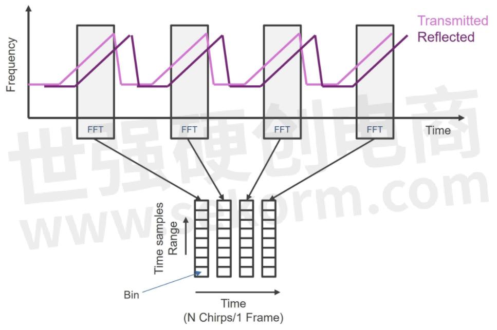
Figure 4: Radar processing: range FFT.
Once all the chips in a frame have been acquired, saved, and processed, the Doppler-FFT is performed to obtain information about the velocity of the target. This evaluation is done once per frame, i.e., every N chirps. Therefore, it is also known as “slow time”. Finally, the data from the spatial along all the available channels are combined, to get the third dimension of the radar cube, which contains the information on the spatial position of the target. The graphic representation of the radar cube is shown in Figure 5.
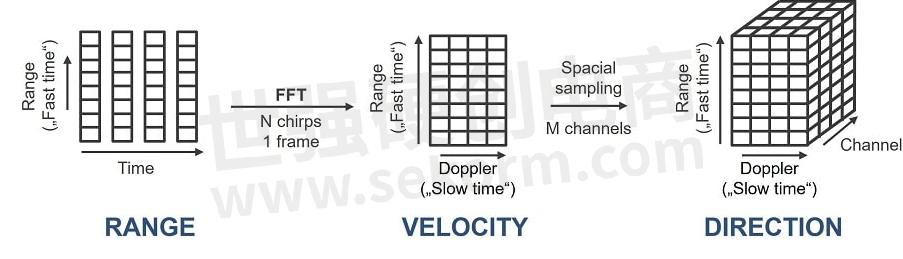
Figure 5: The radar cube.
1.4 Automotive radar modules
The deployment of automotive radar has been facilitated by the advances in the semiconductor technology, especially silicon based. While in the early 2010s multi-channel radar transceivers were integrated on a single GaAs (Gallium arsenide) MMIC (Monolithic microwave Integrated Circuits), nowadays the use of Silicon Germanium (SiGe) has increased the integration density and lowered the costs for mass production. The next challenge will be the transition to CMOS (Complementary metal–oxide–semiconductor), which will allow the integration of further digital circuits on the die while keeping good RF performance.
Yet, to implement a radar system, each radar module must include one or more MMICs transceivers, which emit the radar signal, detect the echoes from the obstacles and perform some signal conditioning and digitation to prepare the raw radar data for further analysis by a processing unit. The later can be a microcontroller unit (MCU) for basic processing, but with the advances in radar technology SoCs (System on Chip) are increasingly used to implement more sophisticated analysis, detection and tracking of the targets.
Figure 6 illustrates the different steps in the processing of the radar signals over the whole receiving path. While analogue RF processing and the conversion to digital signals are always performed on the MMIC, the interfaces for the signal analysis are not fixed. With increasingly complex radar architectures and signal processing, some steps such as the first FFT can already be performed on the MMIC. Moreover, it also possible to combine the radar transceiver and the processing unit in a single, monolithic chip for some applications like corner radars.
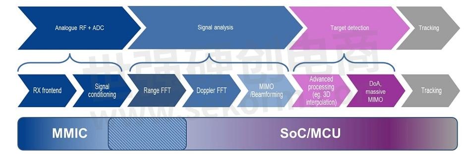
Figure 6: Radar processing steps.
In the future, more complex architectures could be implemented, with several satellite radars distributed around the car. The radar modules would then perform only a limited amount of pre-processing before delivering the data, e.g., range and point cloud, to a central control unit (ECU), which could then apply more advanced processing and data fusion, not only of the satellite radar modules but also of other sensors.
1.5 Conclusion
This entry has provided an overview of the operating principle of the FMCW radar, used in automotive applications, and its implementation using MMICs and MCU/SoC.
- +1 Like
- Add to Favorites
This document is provided by Sekorm Platform for VIP exclusive service. The copyright is owned by Sekorm. Without authorization, any medias, websites or individual are not allowed to reprint. When authorizing the reprint, the link of www.sekorm.com must be indicated.
Recommend

How to Achieve Ultra-Lower Designs Using the RA2E1 MCU and FSP?
2021-12-07 - Design Article How to use the Renesas RA2E1 MCU and Flexible Software Package (FSP) for data logger applications that require low-power consumption for long battery life?

Using Example Projects to Support RA MCU Designs
2022-10-31 - Design Article With the extensive features and offerings supporting the RA MCU family and the Flexible Software Package, Example Projects can augment, simplify, and reduce the MCU design time.

Accelerate Debugging Using RA MCU Innovation Kits for IoT Applications
2021-11-28 - Design Article Renesas RA kits feature three debugging modes: Debug On-board, Debug-Out, and Debug-In. Using these modes, users can not only debug the RA MCU on their RA kit, but also on their custom PCB.

Empowering Intelligent Automotive Applications: Cmsemicon Launches Automotive-Grade SoC Chip BAT32A6300
2024-03-30 - Product Introduction Recently Cmsemicon announced the launch of the BAT32A series automotive-grade SoC chip—BAT32A6300. This chip provides a QFN32 package, meeting the requirements for size- and space-sensitive applications in the automotive body and advanced driver-assistance system (ADAS) domains.

ROHM Partners with Nanjing SemiDrive Technology Ltd., China’s SoC Manufacturer of Next-Generation Cockpits, to Develop Automotive Solutions
2022-09-09 - Manufacturer News ROHM and SemiDrive have been engaged in technology exchange since 2019, mainly on the development of applications for vehicle cockpits. As the first fruits of this effort, SemiDrive’s automotive SoC (X9 series) solution board equipped with ROHM’s PMIC is now available as a solution.

Geehy Showcased a Reliable 32-Bit APM32 MCU Solution at Embedded World 2023
2023-04-14 - Manufacturer News Geehy successfully debuted at Embedded World 2023, showcasing its innovative IC product portfolio and reliable solutions, which included the latest APM32 MCU, Dedicated BMS IC, SoC products and applications in industrial control, new energy, and automotive fields.

RL78/F25, F22 RENESAS Next Gen. Actuator MCU
2023/6/25 - Technical Documentation
NEXT GEN. ACTUATOR MCU,CPU,中央处理器,下一代执行器MCU,MCU,单片机,RL78 FAMILY,RL78/F22,RL78/F23,RL78/F24,RL78/F25,RL78

Renesas RA Family Secure Bootloader for RA2 MCU Series
Feb.4.2022 - Application note & Design Guide
安全引导加载程序,MICROCONTROLLER,微控制器,SECURE BOOTLOADER,MCU,单片机,RA2,RA4,RA6,RA FAMILY

Ultra-Reliable MPC5668G MCU for Automotive and Industrial Gateway Applications
Feb 10, 2025 - Datasheet
MCU,单片机,MPC5668G

Renesas Extends RA MCU Family with RA6T1 MCU Group for Motor Control and AI-based Endpoint Predictive Maintenance
2020-11-04 - Industry News Renesas announced the extension of its microcontroller (MCU) portfolio designed for motor control applications targeting smart homes, industrial automation, and building automation. Featuring a rich set of peripheral functions and AI-based failure detection, the four new RA6T1 Group MCUs are the latest members of Renesas’ rapidly expanding Arm®-based RA Family, and the first RA MCUs designed for the unique needs of motor control in home appliances, HVAC, solar inverters, and AC drives.
RL78/G16 RENESAS MCU DATASHEET
Aug 31, 2023 - Datasheet
MCU,单片机,R5F1214AANA,R5F121BAMFP,R5F1211CASP,R5F1214CASP,R5F1214CMSP,R5F1217CANA,R5F1214C,R5F1214A,R5F1214CGSP,R5F121BAGFP,R5F1217CGNA,R5F121BCAFP,R5F1216CMSP,R5F1211AMSP,R5F1217CMNA,RL78/G16 GROUP,R5F1211AASP,R5F1211AGSP,R5F121BCMNA,R5F1214AMNA,R5F121BCGNA,R5F1214AGNA,R5F1216CASP,RL78/G16,R5F1211C,R5F1216CGSP,R5F1211A,R5F121BCANA,R5F1214AMSP,R5F1214CGNA,R5F121BC,R5F121BA,R5F1214CANA,R5F1214AASP,R5F121BCMFP,R5F1214AGSP,R5F1216C,R5F1217AANA,R5F1216A,R5F121BCGFP,R5F1216AMSP,R5F1217AGNA,R5F121BAAFP,R5F1211CMSP,R5F1211CGSP,R5F1217AMNA,R5F121BAMNA,R5F1217A,R5F1214CMNA,R5F121BAANA,R5F1216AASP,R5F121BAGNA,R5F1217C,R5F1216AGSP,R5F1216CMSP#V0

MCU5 RH850 & RL78 AUTOMOTIVE MCU INTRO
2023年9月 - Selection guide
汽车级微控制器(MCU),系统单芯片(SOC),RH850/F1KM-S1,RH850/F1KM-S4,RH850/P1X-C,RH850/C1M-A,E2X,C1X,F1X,RH850/C1M-A2,RH850/F1KH-D8,RH850/P1X,RL78/F22,U2AX,RL78/F23,RH850/F1X,U2BX,RL78/F13,RL78/F24,RL78/F14,RL78/F25,P1X,RL78/F15,RH850,RL78/F1X,RL78

Renesas R-Car SoC and RH850 MCU to be Used in Honda SENSING System
2022-03-05 - Manufacturer News Renesas Electronics Corporation announced the expansion of its collaboration with Honda in the field of advanced driver-assistance systems (ADAS).

Pairing An R-Car SoC Microprocessor with RH850 and PMIC, System Solution for CoGW ECUs Can Be Realized
2021-01-31 - Application solution Article Our dedicated, system solution for CoGW ECUs can be realized by pairing an R-Car system-on-a-chip (SoC) microprocessor with an RH850 microcontroller (MCU) and various analog chips such as the Power Management Integrated Circuit (PMIC).

RA2 SERIES 32-BIT MCU
JULY 2023 - Supplier and Product Introduction
ARM®CORTEX®-M内核,FAST PROTOTYPING BOARDS,闪光,32-BIT MCU,单片机,快速原型板,32位微控制器,评估套件,ARM® CORTEX®-M CORES,FLASH,EVALUATION KITS,解决方案套件,MCU,SOLUTION KITS,FPB-RA2E2,R7FA2E1A9XXFM#AA0,R7FA2L1AB2DFP#AA0,R7FA2E1A53CFJ#AA0,FPB-RA2E1,RA2,R7FA2A1AB3CFJ#AA0,RSSK-RA2L1,R7FA2A1AB3CFJ,RA2 SERIES,RA2L1,R7FA2A1AB3CFM,RA2E1,RA2E2,EK-RA2L1,RA2A1,RA2A2,R7FA2E1A72DFM,EK-RA2E1,R7FA2E1A93CFL#AA0,EK-RA2E2,EK-RA2A1,RA FAMILY

Electronic Mall


Integrated Circuits


Discrete Components


Connectors & Structural Components


Assembly UnitModules & Accessories


Power Supplies & Power Modules


Electronic Materials


Instrumentation & Test Kit


Electrical Tools & Materials


Mechatronics


Processing & Customization


