Introduction to Common RF Connectors(1)

There are many kinds of radio frequency Connectors(RF Connectors), in order to meet the needs of various frequencies and physical structures. People have designed a variety of connector types, with each type of connector required to meet the corresponding connector standards.
The frequency range of the coaxial connector is limited by the first-order round waveguide mode. Reducing the radius inside of the outer conductor can correspondingly increase the application frequency range, and the operating frequency can be reduced by adding a dielectric material, while also increasing the insertion loss of the connector. The performance of the connector is greatly affected by the quality of the contact surface. If the radius of the inner conductor and the outer conductor is slightly different from the design value, the connection node will be separated, which will increase the port reflection coefficient and lead to large transmission loss. Therefore, the connector machining accuracy will be higher and higher with the increase in application frequency.
This article will focus on the SMA Connector mainly, which is the most widely used in RF circuit design. The typical SMA connector support frequency DC-18GHz, but there are some high-precision types that can support up to 26.5GHz too.
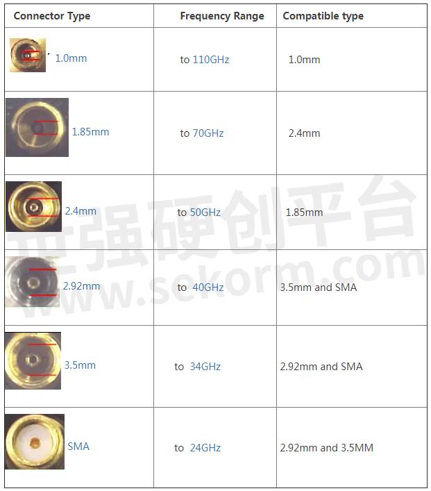
In fact, SMA and 3.5mm (Up to 34GHz), 2.92mm (or K connector, up to 40GHz), both 3.5mm and 2.92mm refer to the coaxial inner diameter of the outer conductor, SMA connectors have foam beads, while 3.5mm and 2.92mm connectors use air interface. On the mechanical structure, these three connectors are compatible, that is to say, the three connectors can be directly connected with each other. But due to the frequency differences, the higher the frequency, the better the performances on mechanical tolerance, stability, temperature, SWR, repeatability, loss, and coating. It means high-level joint damage will be caused when different standard joints are connected with each other. It is strongly recommended to avoid frequent connection of different types of connectors.
Connector appearance drawing and dimensions

Connection criterion:
The improper operation can cause damage to the connector, affecting the measurement results and service life.
Do not connect incompatible RF joints by force.
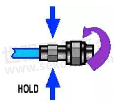
When connecting RF joints, please note that the female head must not be rotated. The correct operation is to rotate the male threaded housing. This helps to reduce the wear between the inner core and the probe and prolongs the service life of the device.

- +1 Like
- Add to Favorites
Recommend
- The Difference between FFC Connectors and FPC Connectors
- Exploring the Benefits of Magnetic Ethernet Connectors in the Electrical Connector Industry
- What is the Role of Industrial Connectors? What Types of Industrial Connectors Can Be Divided into?
- DIN EN 1100 Certified WSMP® Coaxial Connectors, 45% Smaller than Standard SMP Connectors
- Advantages of Smiths Interconnect EMI Filter Connector and Filtered EMP Connectors
- Mission Critical: Maintain your RF cables and connectors 24 APR Mission Critical: Maintain your RF cables and connectors
- Terminal Connection Method of Electrical Connectors
- In-depth Understanding of the Connection Types of Industrial Connectors
This document is provided by Sekorm Platform for VIP exclusive service. The copyright is owned by Sekorm. Without authorization, any medias, websites or individual are not allowed to reprint. When authorizing the reprint, the link of www.sekorm.com must be indicated.


