How to Design A Rectangular Fin Heatsink

The purpose of a heatsink is to acquire higher heat transfer surface area within a given volume by optimizing the structural shape, thereby improving the heat transfer efficiency from its surface to the surrounding fluid. Through surface treatment and other methods, the effective heat transfer area is increased, achieving enhanced cooling and temperature control.
In applications where volumetric power density and heat flux density requirements are not high, rectangular fin heatsinks are favored by engineers due to their simple structure, reasonable manufacturing cost, and good heat dissipation performance.
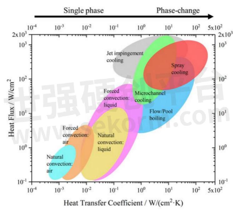
Comparison of different heat transfer methods
1. Heatsink Fin Design
The heatsink primarily extends its heat-dissipating surface through the fins, focusing on parameters like fin height, shape, spacing, and the thickness of the substrate.

Plate fin heat sink dimensions
According to the formula, the extended surface area of the heatsink can be calculated as:
The area of a single fin: Af = 2L(h+t/2),
The area between fins: Ab = Lh,
Total heat dissipation area: At = nAf + (n±1) Ab (n is the number of fins).
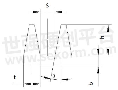
Fin sectional view
The primary function of the fins is to increase surface area and improve heat transfer efficiency. The spacing, thickness, and height of the fins are critical factors in determining the number of fins, their distribution, and the expanded surface area.
When the surface area of the heatsink increases, the contact area with the air also increases, making it easier for heat to be dissipated. Engineers can further enhance the expansion area of the heatsink by optimizing the shape of the fins, such as using corrugated or serrated designs.
Although a larger surface area generally improves cooling performance, it is not always true that bigger is better. Whether using natural convection or forced cooling, the spacing between the heatsink fins is a crucial factor that determines the heat transfer coefficient of the air flowing over its surface.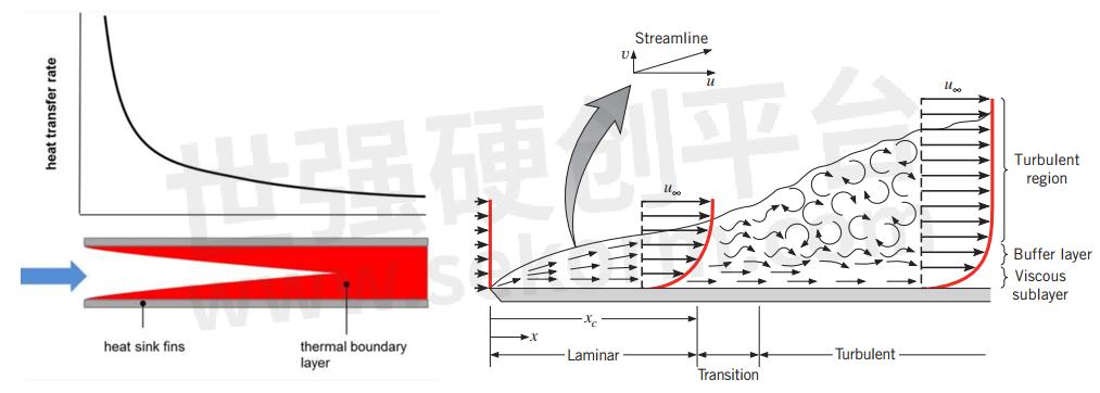
The impact of Fin spacing and height on heat dissipation efficiency
In natural convection, the walls of the heatsink will generate natural convection due to temperature changes on the surface, causing airflow in the boundary layer near the fin walls. If the fin spacing is too small, it will hinder the natural convection process. In forced cooling scenarios, the thickness of the fin boundary layer will be compressed, allowing for narrower fin spacing. However, due to manufacturing methods and the driving force of the power components, the spacing cannot be too small. Therefore, balancing the thickness and height of the fins in actual design is very important.
2. Heatsink Substrate Design
The thickness of the substrate is a significant factor affecting the efficiency of the heatsink. When the heatsink substrate is thin, the thermal resistance to the fins farther from the heat source is larger, leading to uneven temperature distribution across the heatsink and weaker thermal shock resistance.
Increasing the substrate thickness can improve the temperature uniformity and enhance the heat shock resistance of the heatsink, but excessively thick substrates can cause heat accumulation, which in turn reduces thermal conductivity.
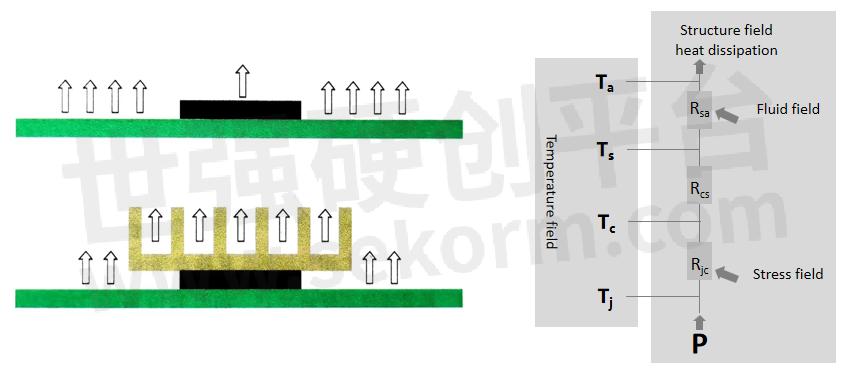
Heatsink working principle diagrammatic sketch
As shown in the figure above:
When the area of the heat source is smaller than the area of the base plate, heat must diffuse from the center to the edges, creating a diffusion thermal resistance. The position of the heat source also affects the diffusion thermal resistance. If the heat source is closer to the edge of the heatsink, heat can be conducted away more easily through the edges, thus reducing diffusion thermal resistance.
Note: Diffusion thermal resistance refers to the resistance encountered during the process of heat spreading from the center of the heat source to the edges of heatsink design. This phenomenon usually occurs when there is a significant difference between the area of the heat source and the area of the base plate, requiring heat to spread from a smaller area to a larger area.
3. Connection Process of Fins and Substrate
The connection process between heatsink fins and the substrate typically involves various methods to ensure good thermal conduction and mechanical stability between the two, mainly divided into two categories: integrated molding and non-integrated molding.
In integrated molding heatsinks, the fins and the heatsink substrate are formed as one piece, eliminating contact thermal resistance. The main processes include:
Aluminum Die Casting: Aluminum ingots are melted into liquid form and then filled into metal molds under high pressure, allowing for the creation of complex fin shapes directly through die casting.
Aluminum Extrusion: Aluminum material is heated and placed into an extrusion cylinder, where pressure is applied to force it through specific die holes, producing the desired cross-sectional shape and dimensions. Further processing includes cutting and machining.

Cold Forging: This method allows for the creation of fine, dense fins with a high thermal conductivity material, but the costs are relatively high, and it has better capability for complex shapes compared to aluminum extrusion.
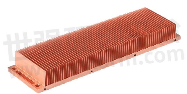
The material for finned heatsinks can be copper, which has a high thermal conductivity. The fins can be made very thin, and they are directly carved from the substrate using cutting tools. However, when the fins are tall and long, they are susceptible to deformation due to stress.
In non-integrated molding, the fins and the heatsink substrate are processed separately and then joined together through welding, riveting, or bonding processes. The main processes include:
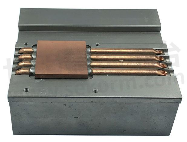
Welding: The fins and substrate are connected together using solder; this can involve high-temperature brazing or low-temperature soldering. Welding has good thermal conductivity; however, using solder for aluminum substrates and fins requires nickel plating and can be costly, making it unsuitable for large heatsinks. Brazing does not require nickel plating, but the welding costs remain high.
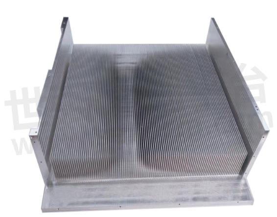
Riveting: The fins are inserted into grooves in the substrate, which are then pressed together with a mold to tightly hold the fins in place. The advantage of riveting is good thermal conductivity, but there is a risk of gaps and loosening after repeated use. Improving the riveting process can enhance reliability, but costs will also increase, so riveted heatsinks are often used in applications where reliability requirements are not high.
Bonding: This generally involves using thermally conductive epoxy resin to tightly bond the fins and substrate together, facilitating heat transfer. While bonding uses thermally conductive epoxy resin, its thermal conductivity is significantly lower than that of welding, making it suitable for heatsinks with higher fins and small spacing. It can be used in scenarios where thermal performance requirements are not high.
- +1 Like
- Add to Favorites
Recommend
- Thermal Design Challenges and Heatsinks Manufacturing
- Understanding the Crucial Role of Heatsinks in Electronics: More Than Just Cooling
- Delta’s High-efficiency Heat Transfer Solutions--Slim Heat Pipes and Slim Vapor Chambers
- What is a Heat Sink Radiator: Unveiling the Secret of Efficient Heat Dissipation
- What Materials Are Used for Heat Sinks?
- What Are the Types of Heat Sinks?
- How to Maintain the Heat Sink?
- A Guide on Aluminium Extrusion
This document is provided by Sekorm Platform for VIP exclusive service. The copyright is owned by Sekorm. Without authorization, any medias, websites or individual are not allowed to reprint. When authorizing the reprint, the link of www.sekorm.com must be indicated.


