Interpreting the Operating Principles and Design Methods of the Popular Wi-Fi Antenna

Recently, a Wi-Fi antenna from Russia went viral in the antenna community. Known for its rugged industrial design and acclaimed for its simplicity in construction and superior antenna performance, it has garnered widespread popularity among enthusiasts. Let's first appreciate this ingenious device.
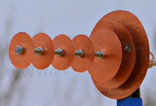
Internet-famous Wi-Fi antenna
The Working Principle of the Legendary Wi-Fi Antenna
Antenna Prototype
In this section, we delve into the operational principles of Russia's famed Wi-Fi antenna, uncovering the secrets behind its capability to receive signals from distances up to 3km. Let's begin our analysis.
Fundamentally, the Russian viral Wi-Fi antenna is an Yagi-Uda antenna. What is a Yagi-Uda antenna, you ask? Refer to the diagram below:
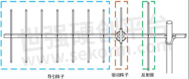
The Yagi-Uda antenna is a type of directional antenna developed in the 1920s by Japanese engineers Hidetsugu Yagi and Shintaro Uda at Tohoku University. It is renowned for its focused emission pattern and high gain, making it suitable for long-distance communications.
The antenna consists primarily of three types of elements: the director elements, driven element, and reflector. All of these elements are mounted on a central metal rod, which serves as the transmission line, as depicted in the diagram below.
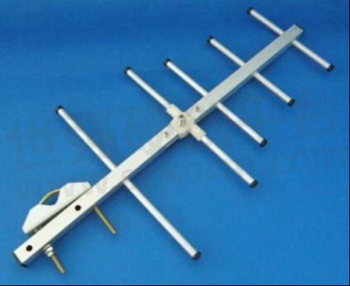
Physical diagram
It belongs to directional antennas, where each driven element and reflector consists of a pair of elements, resembling a dipole antenna. The length of the reflector elements is slightly longer than that of the driven elements. The typical radiation pattern of such antennas is illustrated below:
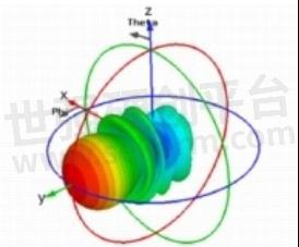
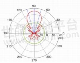
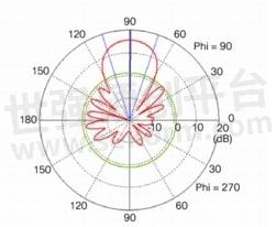
Radiation characteristics of Yagi antenna
The directionality of a Yagi antenna can be enhanced by increasing the number of director elements.
The calculation formulas for the lengths of each element in a Yagi antenna are as follows:
(1) Reflector length: L1 = 150/f
(2) Driven element length: L2 = 143/f
(3) Director element 1 length: L3 = 138/f
(4) Director element 2 length: L4 = 134/f
(5) Director element 3 length: L5 = 130/f
(6) Coaxial feed line length:
From these formulas, the following conclusions can be drawn:
(1) The director elements of the antenna are slightly shorter than half-wavelength.
(2) The driven element equals half-wavelength.
(3) The reflector is slightly longer than half-wavelength, with a spacing of one-quarter wavelength between the elements.
Operation Principle:
For receiving Wi-Fi signals, the director elements of the antenna exhibit capacitive reactance, with current leading voltage by 90°. Electromagnetic waves induced by the director elements will radiate towards the driven element. The radiated signal travels a quarter-wavelength distance, causing a 90° lag that precisely cancels out the leading phase, aligning the phases for signal reinforcement. The reflector, slightly longer than half-wavelength, exhibits inductive reactance with current lagging voltage by 90°. Combined with the additional 90° lag during radiation to the main element, the phases accumulate to exactly 180°, thereby canceling each other out. This reinforcement in one direction and attenuation in another creates directional gain.
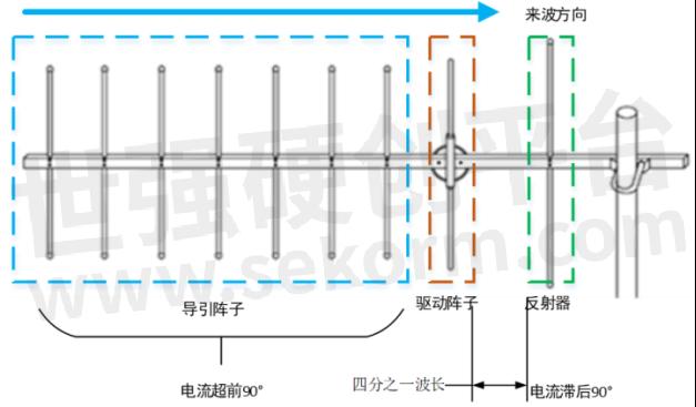
Operating principle of Yagi antenna
Wi-Fi Antenna Design
Antenna Structure
In this section, we will reconstruct the Wi-Fi antenna in HFSS to simulate its performance accurately.
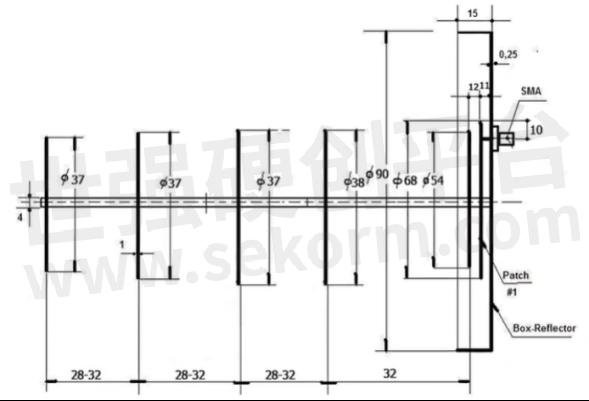
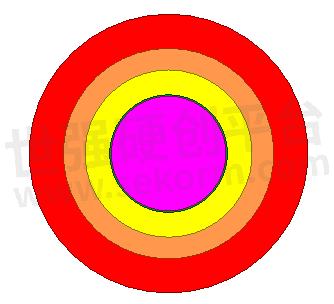
The dimensions of the Russian viral Wi-Fi antenna, as shown in the diagram, consist primarily of seven discs and a metallic rod.
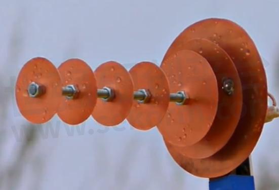
Antenna structure
The sizes of the seven discs are as follows, arranged from smallest to largest:
Disc 1: Diameter 37mm
Disc 2: Diameter 37mm
Disc 3: Diameter 37mm
Disc 4: Diameter 38mm
Disc 5: Diameter 54mm
Disc 6: Diameter 68mm
Disc 7: Diameter 90mm
The spacing between each disc is specified as follows:
Between Disc 1 and Disc 2: 28-32mm
Between Disc 2 and Disc 3: 28-32mm
Between Disc 3 and Disc 4: 28-32mm
Between Disc 4 and Disc 5: 32mm
Between Disc 5 and Disc 6: 12mm
Between Disc 6 and Disc 7: 12mm
Using these dimensions, we will construct the Wi-Fi antenna model in HFSS, as depicted in the diagram below.
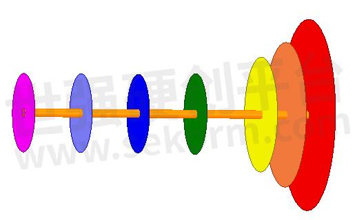
Wi-Fi antenna model
Principle of Operation
The seven discs of this Wi-Fi antenna can be categorized into three zones based on their functions: directors, driven element, and reflector.
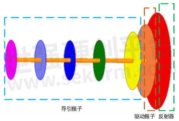
Operation is similar to that of a Yagi antenna: the directors of the antenna exhibit capacitive reactance to induce signals, with current leading voltage by 90 degrees. Electromagnetic waves induced by the directors radiate towards the driven element. Radiated signals travel a quarter wavelength to phase-shift by 90 degrees, precisely canceling out the initial leading phase, resulting in coherent addition of signals.
Analysis Results
After setting up the model and parameters for simulation, the results indicate strong directionality, as depicted in the graph.
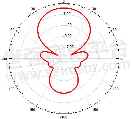
Directivity pattern
The VSWR of this antenna is shown in the graph below. It is evident that the biggest difference compared to a Yagi antenna is that this Wi-Fi antenna does not require a complex impedance matching mechanism to achieve a 50-ohm feed, providing great convenience for antenna enthusiasts in DIY construction.
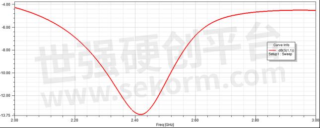
VSWR
Finally, the radiation pattern of this Wi-Fi antenna is depicted, with maximum radiation directed towards the director discs, exhibiting a gain greater than 10 dBi. This explains why it can receive signals beyond 3 km.
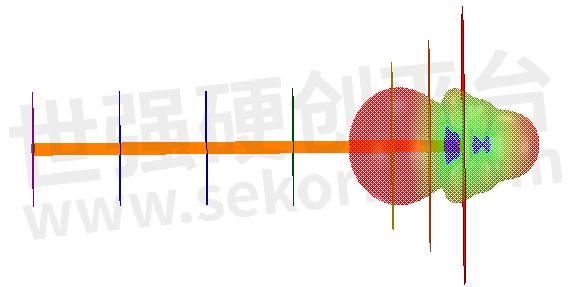
Radiation pattern of the Wi-Fi antenna
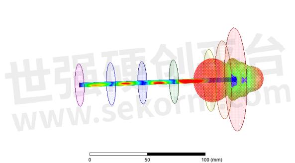
Voltage dynamic graph
Disclaimer: This article is excerpted from Microwave RF Network. Please contact us for removal if there is any infringement.
- +1 Like
- Add to Favorites
Recommend
- TE Connectivity Launches New Linx CW-RCS Series Wi-Fi 6/6E/7 Right-angle Whip Antennas with A Length of Only 54mm
- Ignion Announces the Smallest Virtual Antenna™ at the Wi-Fi World Congress Which is with a size of only 3x2x0.8mm
- AI & Machine Learning: Simplifying IoT Antenna Integration with Virtual Antenna® Technology
- Antenna Intelligence Cloud™ Simplifies Designs with Multiple Antennas
- Revolutionary Virtual Antenna® Solution for Revolutionary Ski Boot Design
- Kinghelm Antennas: Leading the Way with 5.8GHz Technology
- NeuronicWorks Partners with Ignion to Accelerate IoT Device Designs with Virtual Antenna® Solution
- Antenna Design Revolution Powered by AI, Cloud Computing and Machine Learning
This document is provided by Sekorm Platform for VIP exclusive service. The copyright is owned by Sekorm. Without authorization, any medias, websites or individual are not allowed to reprint. When authorizing the reprint, the link of www.sekorm.com must be indicated.


