XBLW Xinbole Analog Chips: Signal Chain Chips (Part 3)

Introduction to Signal Chain Chips: RTC real-time clock chips and serial communication interfaces
Previously, we introduced the rtc real-time clock chips within signal chain chips. Today, we continue our journey into another signal chain chip. Data transfer between computers or between a computer and a terminal employs two methods: serial communication and parallel communication. Serial communication is widely adopted due to its low wire usage, low cost, and particularly its ability to avoid inconsistencies in multiple wire characteristics during long-distance transmission. Our company has developed RS232 and RS422/RS485 serial communication interface chips following the serial data communication interface standard protocols established by the Electronic Industries Alliance (EIA).
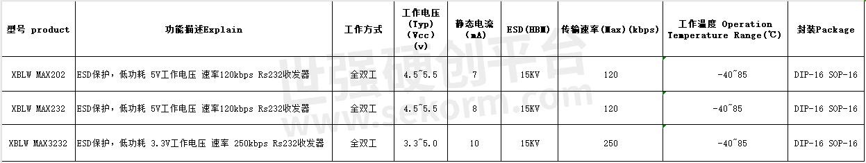
After years of improvements in RS-232 devices and communication technologies, XBLW has introduced three RS232 interface chips that meet market demands. These chips have the following features:
- Compliance with TIA/EIA-232-F and ITU V.28 standards
-High transmission speed, up to 250Kbps
-Wide voltage range, 3.3~5.0V
- I/O pins with over ±15KV ESD protection (HBM)
- Dual drivers and receivers
- DIP-16/SOP-16 packaging
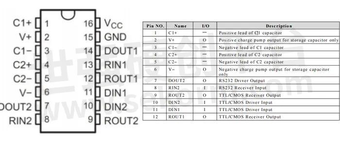
General PIN definitions
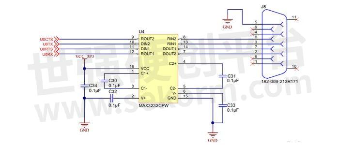
Typical application circuit for RS232 interface chips
Application fields
- Industrial control motherboards
- Optical transceivers
- Industrial controllers
- New energy charging stations
- Programmer downloaders
- Emulators
2. RS422/RS485 Interface Chip
RS485(commonly referred to as RS485/EIA-485) is a standard for electrical characteristics defining a 2-wire, half-duplex, multipoint communication system, differing significantly from RS-232. It uses the voltage difference between the cable ends to transmit signals. RS485 specifies the electrical characteristics for both the receiver and transmitter.
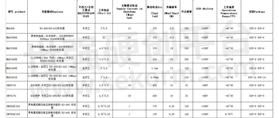
RS485 chip features
1. Low interface level**: RS485 electrical characteristics define logic "1" with voltage difference of +(2 ~ 6)V and logic "0" with a voltage difference of -(2 ~ 6)V. The interface signal level is lower than RS232, reducing the likelihood of damaging the interface circuit chip. This level is also TTL compatible, facilitating connection with TTL circuits.
2. High transmission speed**: at 10 meters, RS485's maximum data transmission speed can reach 35Mbps, while at 1200 meters, the speed can reach 100Kbps.
3. Strong anti-interference ability**: RS485 interfaces use a combination of balanced drivers and differential receivers, enhancing common-mode interference resistance and noise immunity.
4.Long transmission distance and multiple nodes**: RS485 bus can transmit over 1200 meters (speed ≤ 100Kbps) and typically supports up to 256 nodes, with a maximum capacity of 400 nodes.
5. Wide operating voltage range: 3~5.5V
6. I/O pins with over ±15KV ESD protection (HBM)**
7. Low static current: typical value around 300uA
8.Packaging: DIP-8/SOP-8
9. Industrial temperature range: -40~85℃
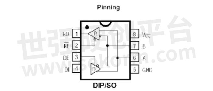
PIN Definitions
Hardware circuit design for RS485 chip
RS485 circuit design can be divided into isolated and non-isolated types. Below is a non-isolated circuit, where the b terminal is pulled down to gnd and the a terminal is pulled high via a resistor to ensure the voltage difference between a and b exceeds 200mv. De and re pins are for send and receive enable; re is low for receive enable, and de is high for send enable. In applications, these two are typically connected together and controlled via an io port (RS485_en). Since the chip is either in send or receive mode, the RS485_en signal is set high for sending data and low for receiving data.

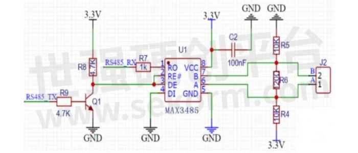
RS485 automatic send-receive circuit hardware design
The automatic send-receive circuit differs from the ordinary 485 circuit by adding a transistor to control the 485 enable pin. R9 is a current-limiting resistor, generally 4.7K, and R8 is a pull-up resistor, also typically 4.7K. The enable pin is pulled high when the transistor is not conducting.

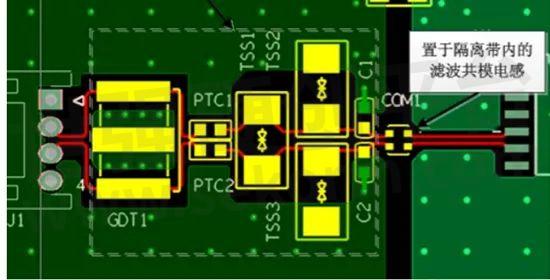
RS485 interface lightning protection circuit design
GND design for RS485 interface circuit PCB
Protective devices indicated by dashed lines should be placed as close to the interface as possible, arranged compactly and neatly, with protective devices placed before filter devices.
Application fields
-Industrial automation: RS485 is often used for communication between plcs (programmable logic controllers) to enable data exchange between devices. Industrial buses based on RS485, such as modbus and profibus, are widely used for connecting multiple devices to achieve remote monitoring and control.
-Building automation: RS485 is frequently used for the control and management of intelligent buildings. Through the RS485 bus, various devices (e.g., lighting systems, air conditioning systems, security systems) can be connected to a centralized management system for remote monitoring, adjustment, and management.
-Data acquisition and monitoring systems: RS485 interfaces can connect multiple sensors and actuators, transmitting real-time environmental data to a central processor or monitoring system for real-time monitoring and control of environmental parameters.
XBLW has launched various RS232 and RS422/ RS485 serial communication interface chips, which have been widely applied in industrial control, instrumentation, multimedia networks, and mechatronics products. Our company can provide reasonable guidance on chip selection and circuit design based on user needs. We hope this article helps you understand RS232 and RS422/ RS-485 interface chips better.
- +1 Like
- Add to Favorites
Recommend
- XBLW Showcased Linear Voltage Regulator XBLW AMS1117, RS-485/RS-422 Chip MAX3485 and Other Product in 2023 ES SHOW
- Application Of XBLW Products On Fascia Guns
- Real-Time Clock (RTC) Chips XBLW DS1302 & DS1307: Powerful And Reliable
- Programmable Resolution Single-Bus Temperature Sensor - XBLW DS18B20 Offers Temperature Measurement With A Resolution of 9 To 12 Bits
- Xinbole (XBLW) Attended the Shanghai Munich Electronics Show, July 8-10, 2024
- The Linear Regulator XBLW AMS1117 with Output Current Capability up to 1A and Output Voltage Accuracy of ±1.5%
- A Introduction to The Power Management Chips from Xinbole XBLW - Analog Chips
- XBLW MIC29302 Low Dropout High Current Adjustable Regulator with a Maximum Input Voltage up to 26V
This document is provided by Sekorm Platform for VIP exclusive service. The copyright is owned by Sekorm. Without authorization, any medias, websites or individual are not allowed to reprint. When authorizing the reprint, the link of www.sekorm.com must be indicated.
Integrated Circuits


Discrete Components


Connectors & Structural Components


Assembly UnitModules & Accessories


Power Supplies & Power Modules


Electronic Materials


Instrumentation & Test Kit


Electrical Tools & Materials


Mechatronics


Processing & Customization


