Few Tips for Proper Oscillating Circuit Design

The function of a quartz crystal resonator is locking and determines the oscillation frequency of an oscillating circuit which is widely used in electronic industries. Proper circuit design and components configuration is crucial to the stability of oscillating circuits with quartz crystal resonators overtime.
How can we know the oscillating circuit using a crystal resonator is properly designed? What shall hardware engineers consider? Interquip Electronics, the manufacturer of quartz crystal resonators and Oscillators, would like to share some basic tips:
Negative Resistance
Drive Level
On-board oscillating frequency
Negative Resistance of the oscillating circuit
Negative resistance (-R) is a parameter of an oscillating circuit that is determined by the gain and terminated capacitances which shall be large enough to ensure a reliable oscillation.
According to the basic rule, the negative feedback loop gain of an oscillation circuit shall be greater than 1 to sustain an oscillation. |-R| divided by Rr represents the negative gain of the oscillating circuit approximately. The recommendations from IEC60444-6 is |-R| / Rr shall be greater than or equal to 3 for reliable oscillation and Rr shall be the maximum Rr in all circumstances. Interquip Electronics recommends 5 times or more which has a better design margin.
The Drive Level of the oscillation circuit
A quartz crystal resonator is a piezoelectric device. The piezoelectric effect provides a coupling between the mechanical properties of a piezoelectric crystal and an electrical circuit. Below is the bulk acoustic wave mode of an AT cut quartz crystal resonator,
The mechanical displacement is proportional to the drive level (power) applied. It induces stress and causes irreversible damage over time in some circumstances if the drive level is extremely large. 1uW to 100uW is recommended for AT cut Mhz quartz crystal resonators in general.
The drive level is equal to,
DL=Ix2*RL
RL: Load resistance, which is equal to Rr(1+C0/CL)²
Ix: the current goes through the quartz crystal resonator
C0: Shunt capacitance of quartz crystal resonator
CL: equivalent load capacitance
Ix is the current go thru the quartz crystal resonator which could be measured using a high-frequency current probe.
On board oscillation frequency
The on board oscillating frequency is determined by the quartz crystal resonator characteristic and the on board equivalent load capacitance. The on board equivalent load capacitance CPCB is related to Cg/Cd, terminal capacitance of the integrated circuit (CIC), and stray capacitance (Cs) on board as below:
CPCB= (Cg + CIC)×(Cd + CIC)/(Cg + Cd + 2 x CIC) + Cs
The quartz crystal resonator frequency is load capacitance (CL) dependent. It is tuned by the manufacturer to the desired tolerance per specification. The on board oscillating frequency shall be within the frequency tolerance when the on board equivalent load capacitance is the same as the CL specification of the quartz crystal resonator. Otherwise, the on board oscillating frequency will deviate from the nominal frequency. If that happens, adjust Cg and Cd when necessary.
In addition, it shall be caution when measuring the on board oscillating frequency. The probe capacitance could be part of the on board equivalent load capacitance that contributes to measurement error. A non-contact measurement using a spectrum analyzer or equivalent is recommended.
In short, engineers shall verify the negative resistance of the oscillating circuit, the drive level, and the on-board oscillating frequency when the design of the oscillation circuit is determined. Adjust the circuit component to optimize the performance and lower the risk when necessary.
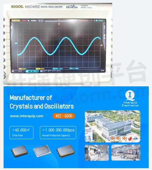
Interquip Electronics is a comprehensive high-tech enterprise in R&D, manufacturing and marketing high precision Quartz Crystal Resonators (including self-developed material SMCM series, Thermistor Crystals, and 32.768KHz Tuning Fork Crystals) and Oscillators (including TCXO, VCXO, LVDS output waveform SPXO/LVPECL output waveform SPXO, programmable Oscillators etc.). The size of crystal resonators and oscillators ranges from 1.2 x 1.0mm to 5.0 x 3.2 mm package, with frequencies available from 32.768KHz to 200MHz. The frequency components produced can be widely applied in 5G Smart Home, Smart Wear, IoT, IoV, Consumer Electronics, Telemedicine, Automotive Electronics (conforms to AEC-Q200), Communication Industry, Security Applications, Industrial Equipment, and other industries.
- +1 Like
- Add to Favorites
Recommend
- The Difference Between a Quartz Crystal Resonator and a Quartz Crystal Oscillator
- Working Principle of Crystal Resonator
- There are Two Main Types of Crystal Oscillators: Active Crystal Oscillators and Passive Crystal Oscillators
- Does a Passive Crystal Oscillator Have a Direction?
- Tips for Crystal Oscillator Circuit Design, Essential Skills for Engineers!
- How to Prevent the Bad Phenomenon of Crystal Vibration?
- Main Functional Materials of Quartz Crystal Resonators
- Child Presence Detection-Aker C1E Crystal Series Meet the Accuracy Requirements for CPD Applications
This document is provided by Sekorm Platform for VIP exclusive service. The copyright is owned by Sekorm. Without authorization, any medias, websites or individual are not allowed to reprint. When authorizing the reprint, the link of www.sekorm.com must be indicated.
Integrated Circuits


Discrete Components


Connectors & Structural Components


Assembly UnitModules & Accessories


Power Supplies & Power Modules


Electronic Materials


Instrumentation & Test Kit


Electrical Tools & Materials


Mechatronics


Processing & Customization


